HELIOS LED Processing Platform - USER GUIDE 3
Indicator Color Meaning
White System boot
Black No link (no cable)
Yellow Valid link, no video
Blue Valid link, valid video
Red Error detected in the last 1.25 sec
Green / Cyan / Magenta Training cycle
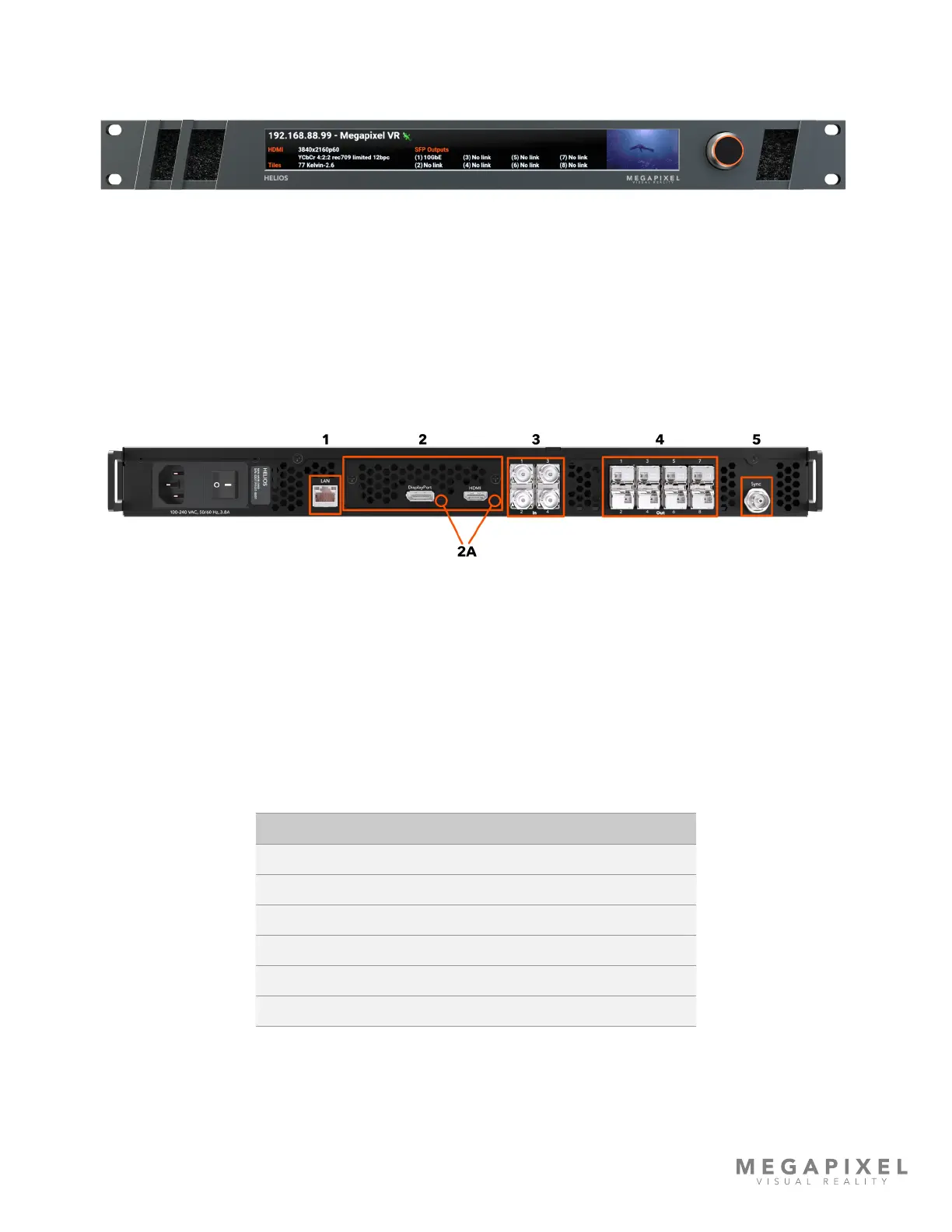
Processor Front Panel
Figure 3: HELIOS Processor front.
Conguration Interface - on the front of the HELIOS Processor is an LCD display and a turn/push knob interface.
Air Inlets - slots to the left and right of the LCD display are ltered vents for chassis airow.
Processor Rear Panel
Figure 4: HELIOS Processor rear.
1 - Control Port - On the left side is an Ethernet port. This port should be used to place the processor on the system
control LAN. A laptop may directly connect, or in larger systems a wireless router connects here.
2 - VFMC Video Inputs - The video inputs are modular. At the center of the unit is a removable plate that houses
removable VFMC input boards. The HELIOS system supports HDMI and DisplayPort cards in these slots. HELIOS units can
be congured with dual HDMI or dual DisplayPort cards.
2A - VFMC Video Input Indicators - Next to each video input connector is a small LED that indicates the status of each
VFMC input link.