37
2.1.6.3 Terminal description
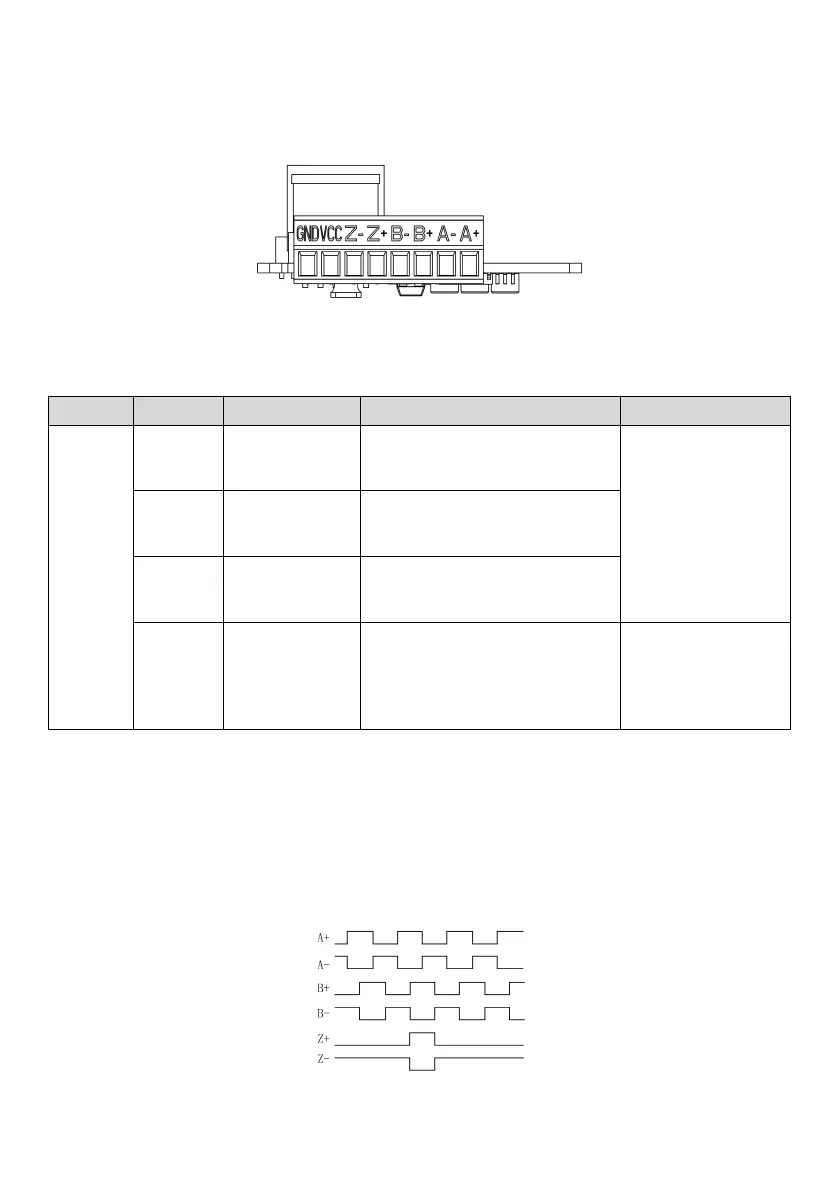
The following figure shows the marks of terminals on the MV810-PG01 speed measurement card.
Fig. 2-14 Terminal mark
Table 2-11 lists the pin definition of terminals on the MV810-PG01 speed measurement card.
Table 2-11 PG01 terminal functions
Encoder phase A differential input signal
Maximum input
frequency
≤
250 kHz
Encoder phase B differential input signal
Encoder phase Z differential input signal
Provides power supply for external
encoders (reference ground GND),
5 V or 12 V set by P04.04
Output voltage: +5 V/12 V
Maximum output current:
200 mA/150 mA
2.1.6.4 Signal description
The ABZ signal waveform of the MV810-PG01 speed measurement card is shown in Fig. 2-15 below. When the motor
rotates forward (the operating frequency is positive), phase A leads phase B by 90 degrees. Conversely, phase A lags
behind phase B by 90 degrees. The Z signal is used to provide the absolute position information for correction of
counting and locating of initial position. One Z signal is sent for each revolution of the encoder.
Fig. 2-15 ABZ signal waveform