58
Notes:
(1) The GND terminal should be connected to the 0 V of an external device.
(2) AI1 and AI2 can be set to input voltage signals or current signals through the function codes P09.01 and P09.02.
(3) AO1 can be set to output voltage signals or current signals through the function code P09.02.
(4) If external braking components are required, an external braking resistor should be connected. See the model
selection of braking resistors in the Appendix 2.
(5) In the figure, “ ” means main circuit terminals and “ ” means control circuit terminals.
(6) To use control circuit terminals, refer to section 4.2.
(7) The above basic wiring figure takes a three-phase model as the example. The actual wiring depends on the specific
model.
4.2 Control circuit terminal wiring and description
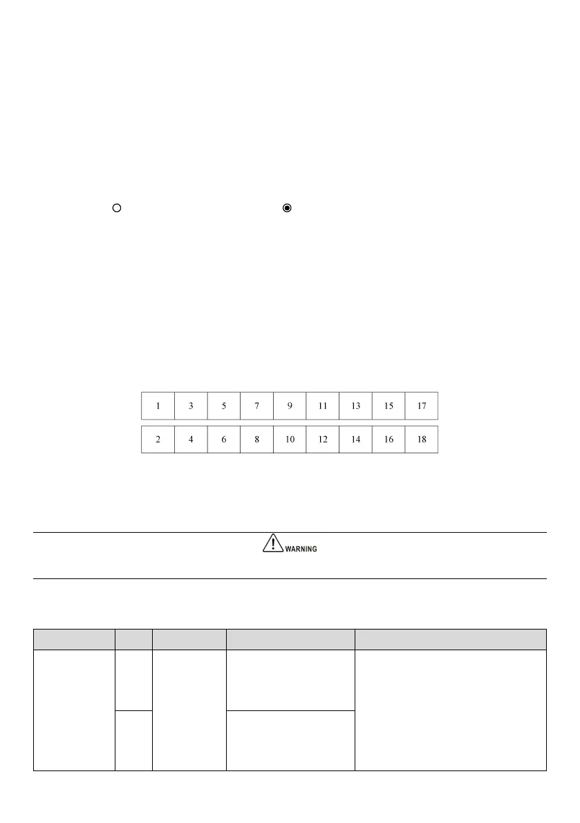
4.2.1 Control circuit terminal layout
Fig. 4-4 Control circuit terminal layout
4.2.2 Control circuit terminal wiring
It is recommended to use wires above 0.5 mm
2
for connection of control circuit terminals.
The terminal functions are shown in Table 4-5.
Table 4-5 Terminal functions of the interface board
485 differential signal
positive (reference ground:
GND)
Standard RS485 communication interface
Use twisted pair cables or shielded cables
485 differential signal
negative (reference ground:
GND)
 Loading...