Home
Megmeet
Controller
MV820
Page 76 (Grounding)
Megmeet MV820 - Grounding
323 pages
Manual
Save Page as PDF
To Next Page
To Next Page
To Previous Page
To Previous Page
Loading...
76
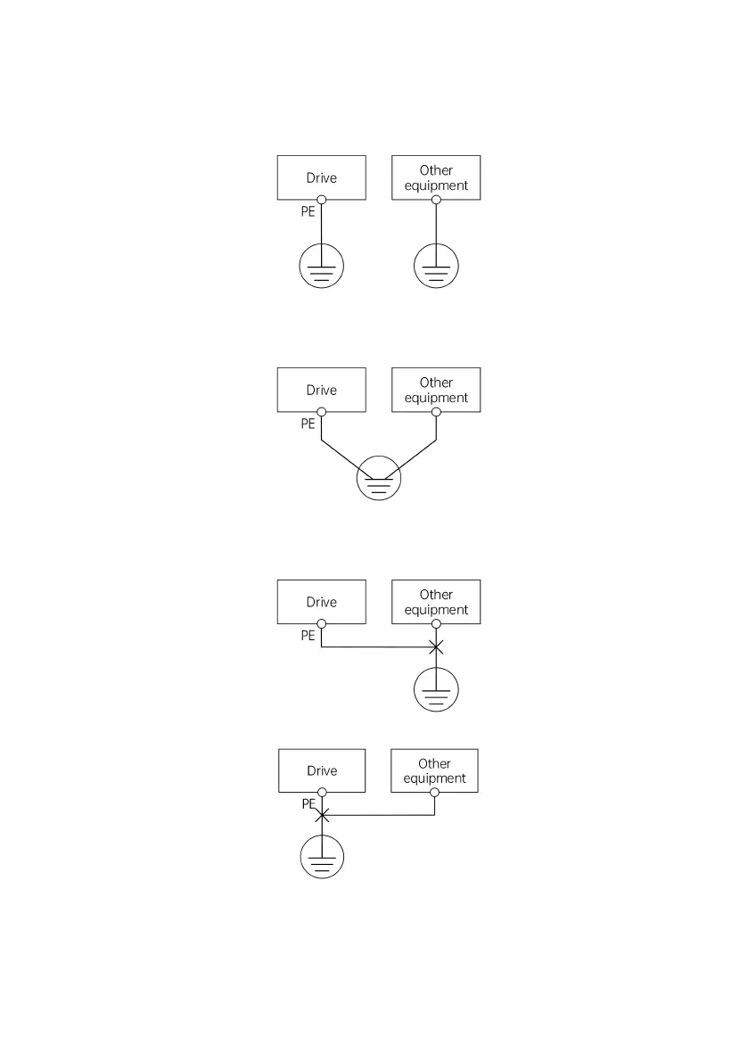
4.3.3
Grou
nding
Dedicated
grounding
pole
(the
best
)
Fig.
4-29
Grounding
diagram
1
Shared
grounding
pole
(
acc
eptable)
Fig.
4-30
Grounding
diagram
2
Shared
grounding
cable
(unacceptable)
Fig.
4-31
Grounding
diagram
3
Fig.
4-32
Grounding
diagram
4
75
77
Table of Contents
Main Page
default chapter
5
Table of Contents
5
Chapter 1 Introduction of MV820 Series
9
Product Model
9
Product Nameplate
9
Product Series
10
Technical Specifications
10
Product Components
14
Product Dimensions
14
Operating Panel Dimensions
17
Chapter 2 Options and Accessories
19
Accessory Cards/Options
19
Installation of Accessory Cards/Options
19
MV810-PNET01: PROFINET Communication Option
24
MV810-ECAT01: Ethercat Communication Option
27
MV810-ECAT02: Ethercat Communication Option
31
MV810-IO01: Simple IO Option
35
MV810-PG01: Simple Incremental ABZ Encoder Card
36
Other Accessories
38
Dustproof Kit
38
Embedded Mounting Bracket Kit
38
Reinforced Metal Bottom Plate
40
Wire Fixation Bracket
40
Guide Rail Bracket
40
Keypad/Operating Panel Mounting Base
41
Remote LED Keypad/Operating Panel (with Shuttle)
42
Remote LCD Keypad/Operating Panel (in Development)
43
Braking Unit (See
43
Chapter 3 Drive Installation
44
Assembly/Disassembly of Drive Components
44
Installation Environment
45
Installation Direction and Gap
45
Chapter 4 Drive Wiring
47
Main Circuit Terminal Wiring and Description
50
Main Circuit Input and Output Terminal Types
50
Connection of Drive and Accessories
53
Basic Operation Wiring
57
Control Circuit Terminal Wiring and Description
58
Control Circuit Terminal Layout
58
Control Circuit Terminal Wiring
58
Drawing of Control Board
71
Installation Instructions for EMC Requirements
72
Noise Suppression
72
Field Wiring Requirements
74
Grounding
76
Installation of Relay, Contactor and Electromagnetic Brake
77
Leakage Current and Measures
78
Proper EMC Installation of Drive
79
Operating Instructions for Power Filter
82
Drive Radiation Emission
82
Chapter 5 Quick Operation Guide for Drive
84
Operating Panel
84
Introduction
84
Identification of LED Display Symbols
88
Basic Operations
89
Operation Mode
92
Operation Command Channel
92
Operation Status
93
Control Mode and Operation Mode
93
Drive Frequency and Torque Channel
94
Initial Power-On
95
Inspection before Power-On
95
Initial Power-On Operation
96
Chapter 6 Parameter List
97
Explanation of Terms Related to Function Codes
97
Function Codes of Basic Menu
97
Chapter 7 Parameter Description
181
P00: System Management Parameters
181
P01: Status Display Parameters
184
P02: Basic Function Parameters
189
P03: Motor 1 Parameters
195
P04: Motor 1 Encoder Parameters
198
P05: Motor 1 Vector Control Parameters
200
P06: Motor 1 Torque Control Parameters
205
P07: Motor 1 V/F Control Parameters
208
P08: Startup/Stop Control Parameters
211
P09: Terminal Input Parameters
216
P10: Terminal Output Parameters
230
P11: Auxiliary Function Parameters
235
P12: Control Optimization Parameters
242
P13: Multi-Speed and Simple PLC Parameters
242
P14: Process PID Parameters
249
P15: Communication Parameters
255
P16: Keypad Display Setting Parameters
257
P20: Motor 2 Parameters
259
P21: Motor 2 Encoder Parameters
261
P22: Motor 2 Vector Control Parameters
262
P23: Motor 2 Torque Control Parameters
262
P24: Motor 2 V/F Control Parameters
263
P40: Fieldbus Option Parameters
265
P41: IO Option Parameters
265
P43: PROFINET Communication Parameters
267
P50: Option Status Parameters
269
P97: Fault and Protection Parameters
270
P98: Drive Parameters
276
Chapter 8 Troubleshooting
278
List of Fault Codes
278
List of Operation Exceptions
284
Chapter 9 Maintenance
287
Daily Inspection
287
Periodical Maintenance
288
Replacing Wearing Parts
289
Storage of Drive
290
Chapter 10 Application of Special Functions
291
Closed-Loop Application
291
Integrated Communication Application
292
Appendix 1 Modbus Communication Protocol
295
Appendix 2 Braking Components
314
Appendix 3 Warranty and Service
318
Parameter Recording Table
320
Wiring Diagram
322
Related product manuals
Megmeet MC100 Series
5 pages
Megmeet MC200E Series
4 pages