70
(4) During wiring, the control cables shall be kept away from the main circuit and the strong current lines (including the
power cable, motor cable, relay cable, contactor connection cable, etc.) for at least 20 cm, and they shall not be laid
in a parallel way. The vertical wiring is recommended to reduce interference and avoid misoperation of the drive.
(5) For the non-24 V relay, an appropriate resistor shall be selected according to the relay parameters and connected in
series to the relay circuit.
(6) The digital output terminals can not withstand a voltage over 30 V.
4.2.2.7 Notes for encoder wiring
The encoder (PG) signal cable shall be kept away from the main circuit and other power cables, and parallel wiring with
narrow clearance is strictly forbidden. The shield cable is required for encoder wiring, and the shield layer (near the drive)
shall be connected to PE.
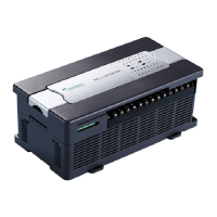
(1) When the PG output signal is an open-collector signal, the wiring with the interface board is as shown in Fig. 4-20
(the broken line in the figure is the voltage-type output encoder):
Fig. 4-20 Wiring diagram for open-collector PG
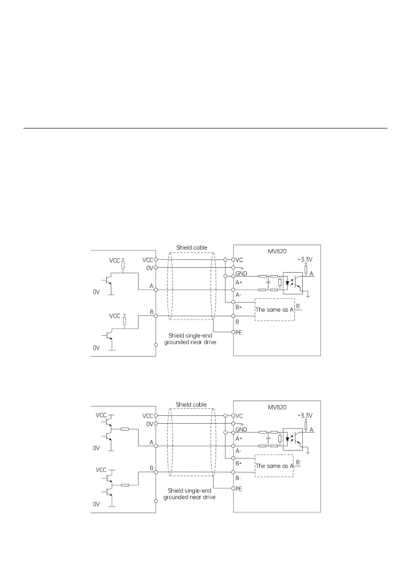
(2) When the PG output signal is a push-pull signal, the wiring with the interface board is as shown in Fig. 4-21:
Fig. 4-21 Wiring diagram for push-pull PG
 Loading...