SECTION 5
DISASSEMBLY AND ASSEMBLY
106
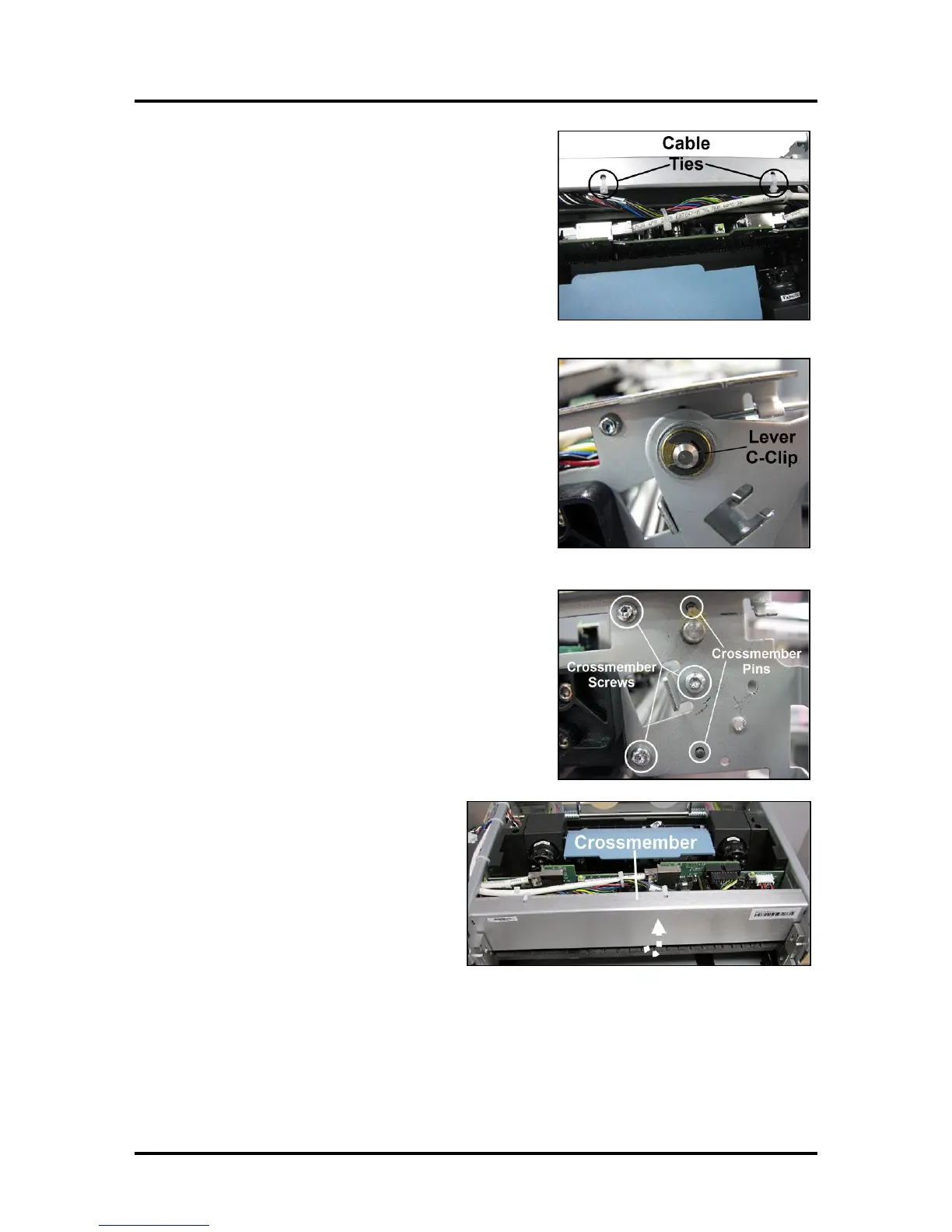
5. Cut and remove the (2) cable ties holding the wire
harness to the Print Engine Frame Crossmember.
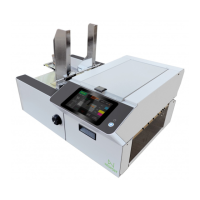
6. Remove Latch Levers (both sides). Carefully remove
the C-clip holding the Latch Lever onto the Upper
Latch Pin. DO NOT LOSE! Must be reinstalled later.
Repeat the procedure for the Latch Lever on the
other side.
7. Slide the Latch Lever and Spring off of the Upper
Latch Pin. NOTE: You may have to separate the
Lever from the Spring. Repeat procedure on the
other side.
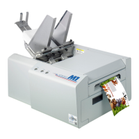
8. Remove the Print Engine Frame Crossmember.
Remove the (3) screws securing the Crossmember to
the Print Engine Side Frame. Repeat procedure for
the other side.
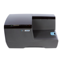
9. Carefully pull the Side Frames away
from the Crossmember to slide it off the
lower mounting pins. Pivot the bottom of
the Crossmember up and carefully
remove the Crossmember from the upper
mounting pins.


 To Next Page