SECTION 6
DISASSEMBLY AND ASSEMBLY
61
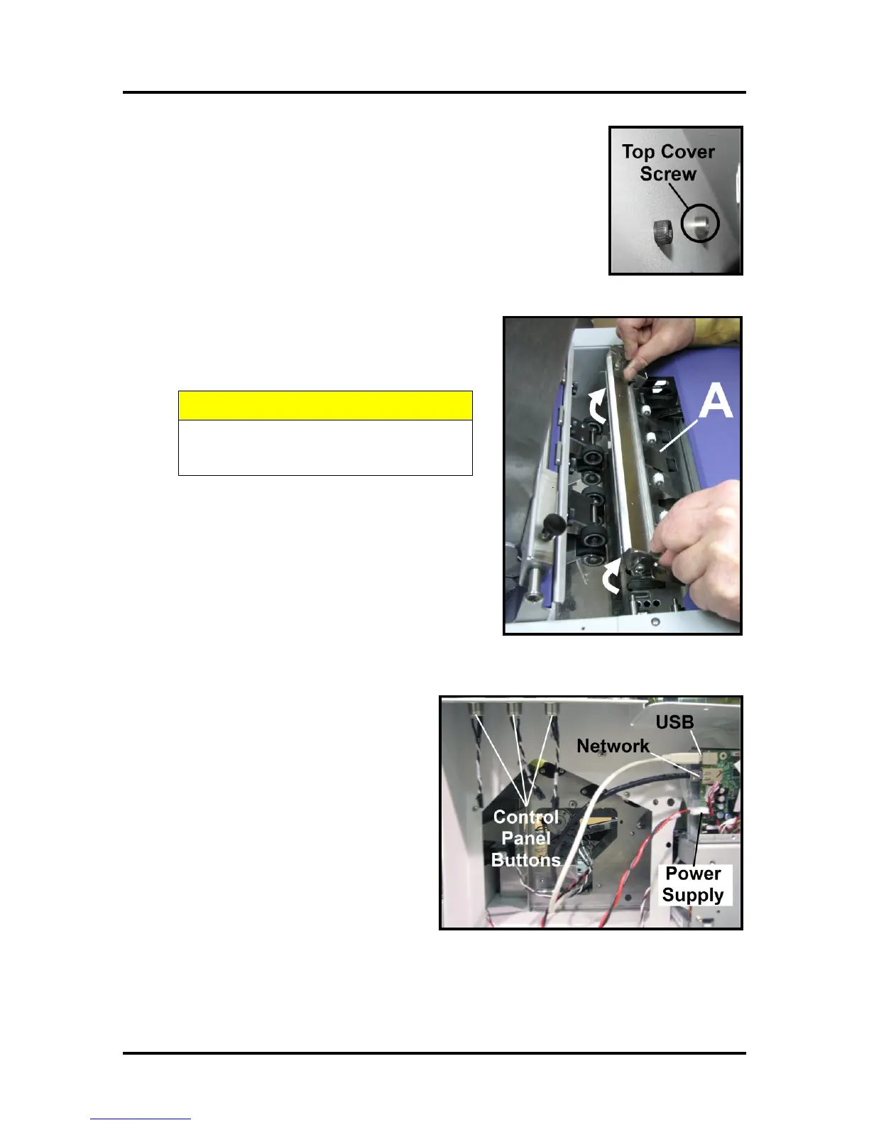
4. Remove Top Cover. Remove “cover pivot screw” on right-hand side
(non-operators side). Remove Top Cover and set aside.
Tip: To save time; you can skip this step. Top cover will be released
once you remove the operator side-frame (step 8).
5. Remove Antistatic Brush Assembly [A] from
mounting studs. Unlatch the two latches (one on either
side of the Assembly) and lift the assembly off the four
mounting pins as shown. Do not bend the brushes!
DO NOT BEND, PINCH OR CUT THE INK
LINES LOCATED DIRECTLY IN FRONT
NOTE – Make sure Brush Assembly is correctly reinstalled
and aligned before starting to print. Assembly should sit
flat on transport area surface.
6. Unplug Network, USB and Main Power
connectors from Print Engine Circuit
Board. Disconnect the wires attached to the
Power, Paper and Cancel Buttons at
connectors. NOTE: Wires are labeled to
simplify reconnection.