DUAL POWER TRIM SYSTEM SERVICE MANUAL NUMBER 28
Page 5C-2 90-863160 MAY 2000
Important Information
When testing this Dual Power Trim system, take special note of the following:
• The control box harness connectors must be disconnected and the key switch must
be OFF.
• Make certain that the jumper lead used between terminals 3 and 5 is used only when
specified.
The following tests are listed in order of probable component failure. It is recommended,
however, that all tests be performed even if a faulty component is detected early in the
sequence. This precaution will guard against repeat failure if there is more than one failed
component.
Testing Dual Power Trim System
22129
e
c
a
b
d
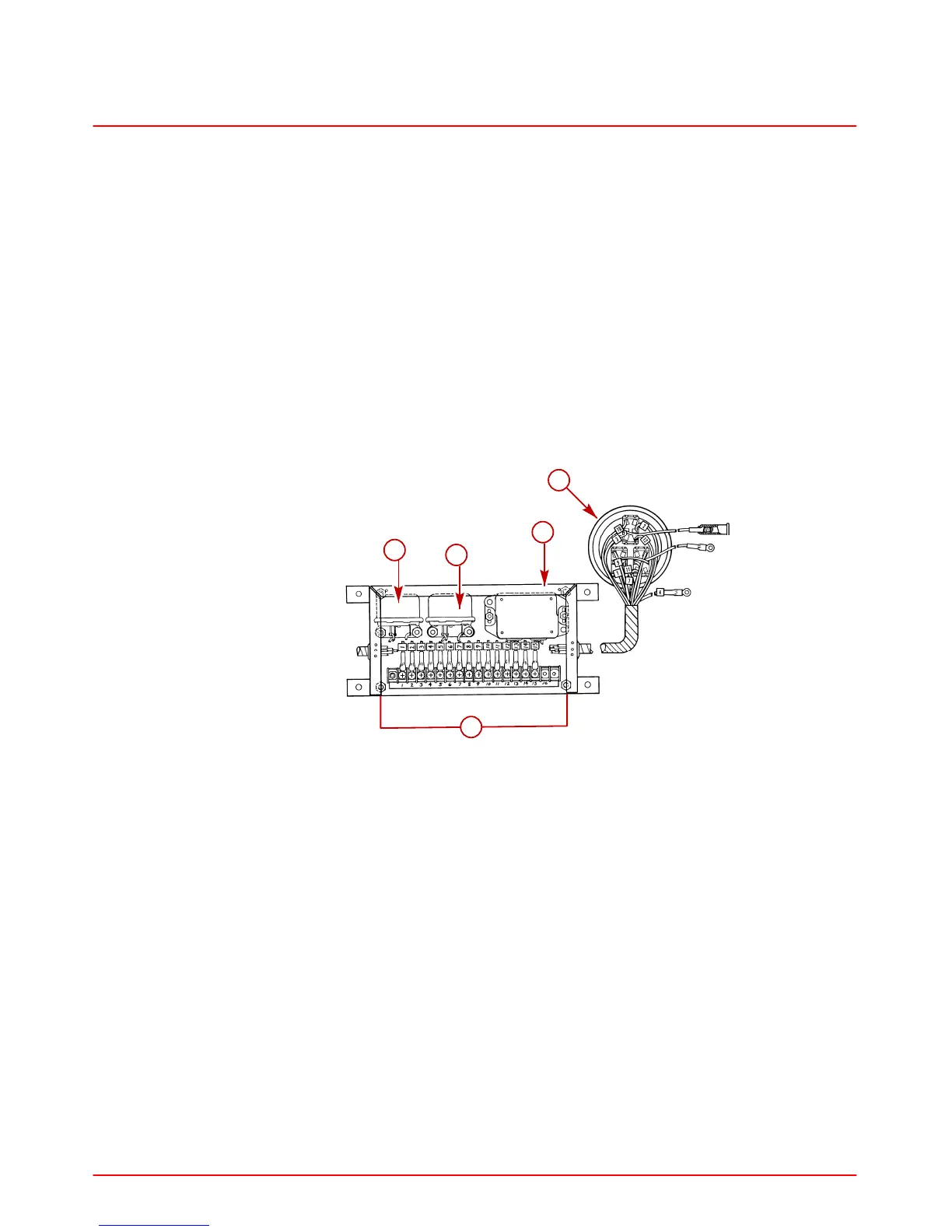
Dual Trim Control Panel Electrical Box
a-Relay No. 1
b-Relay No. 2
c-Diode Module
d-Terminal Block
e-Control Panel
Relay Test
TESTING RELAY NO. 1
1. Test for 12 volts at terminal 2, using only terminal 4 as a ground.
• Voltage indicated, proceed to “2.”
• No voltage indicated, replace relay.
2. Connect a jumper wire between terminals 3 and 5. Test for 12 volts at terminal 2, using
only terminal 4 as a ground.
• No voltage indicated, relay OK.
• Voltage indicated, replace the relay.
 Loading...