Bulletin No. 3020IB9814
December 1998
10
o AMMETER (A)
o VOLTMETER, L-L (V)
o VOLTMETER, L-N (V)
o WATTMETER (W)
o VARMETER (VAr)
o VA METER (VA)
o POWER FACTOR METER
o FREQUENCY METER (Hz)
o DEMAND AMMETER (A)
o DEMAND POWER (W)
o DEMAND POWER (VA)
o WATTHOUR METER
o VARHOUR METER
o THD, CURRENT (%)
o THD, VOLTAGE (%)
o K-FACTOR
CIRCUIT MONITOR
[CT Primary]
[PT Primary]
[Sys. Type]
[Dmd. Int.]
[WH/Pulse]
[Address]
[Baud Rate]
[Nom. Freq.]
[Reset]
[Reset]
[Reset]
[Reset]
[Reset]
[Rst. Min/Max]
[Set Password]
[Accept]
3-PHASE
A (A-B)
B (B-C)
C (C-A)
N
SELECT
METER
[Value]
METERS
MIN
MAX
ALARM
[Setup]
Kilo
Mega
PHASE
MODE
Optical
Comm Port
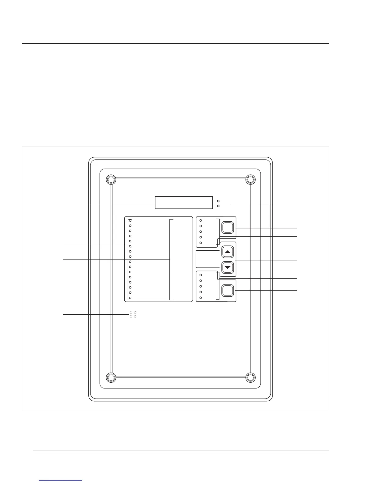
➇ Mode Indication LEDs. These LEDs indicate the present display mode.
The Alarm LED flashes when an alarm is active.
➈ MODE Select Button. Press to select the display mode.
➉ Optical Communications Port. This port allows the circuit monitor to
communicate to a portable computer using the optional optical
communications interface (Class 3090 Type OCI-2000). The OCI-2000
mounts magnetically to the circuit monitor and provides a standard
RS-232 interface. Anything that can be done over the RS-485
communications link—including circuit monitor setup—can also be done
using the optical communications port.
Figure 2-1: Circuit monitor front panel
➅
➆
➁
➀
➉
➇
➈
➄
➂
➃
 Loading...