Bulletin No. 3020IB9814
December 1998
28
(+)L G N(-)
56781234
I
a+
I
a-
I
b+
I
b-
I
c+
I
c-
I
n+
I
n-
25 26 27
AUXILIARY
CURRENT
INPUTS
5 AMPS
NOMINAL
3 PHASE
CURRENT
INPUTS
5 AMPS
NOMINAL
CONTROL
POWER
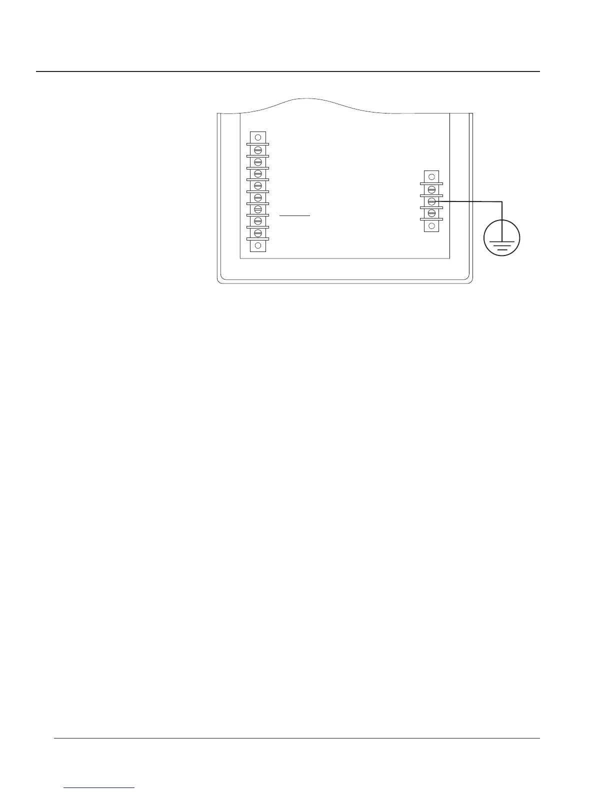
#14 AWG Wire
(or Larger)
True Earth
Ground
Figure 3-14: Grounding the circuit monitor
COMMUNICATIONS WIRING POWERLOGIC devices are equipped with RS-485 communications. The
RS-485 standard lets you daisy-chain up to 32 POWERLOGIC-compatible
devices to a single communications port. This document refers to a chain of
POWERLOGIC devices connected by communications cable as a
communications link.
A POWERLOGIC communications link can consist of up to 32
POWERLOGIC-compatible devices connected to a communications port on
one of the following:
• POWERLOGIC System Display
• Personal computer
• POWERLOGIC Network Interface Module
• SY/MAX
programmable controller
• Other host devices with a POWERLOGIC-compatible port
Figures 3-15 through 3-19 show circuit monitors and other POWERLOGIC
compatible devices connected in typical systems. The accompanying text
describes important considerations for each connection alternative.
The figures also show the placement of communications adapters and
terminators. For additional information on using the communications
adapter and terminator, see Terminating the Communications Link and
Biasing the Communications Link in this chapter.
 Loading...