Bulletin No. 3020IB9814
December 1998
32
Connecting to a POWERLOGIC • Connect up to 32 POWERLOGIC devices to a PNIM. See Length of the
Network Interface Module Communications Link in this chapter for distance limitations at different
(PNIM) baud rates.
• Connect POWERLOGIC devices to PNIM port 0 (top RS-485 port) only.
• Configure PNIM port 0 for “POWERLOGIC” mode. (See side of PNIM for
instructions on setting dip switches.
• Configure the baud rate of PNIM port 0 to match the baud rate of the
POWERLOGIC devices on the communications link.
• Refer to the PNIM instruction bulletin for detailed instructions on
configuring the PNIM.
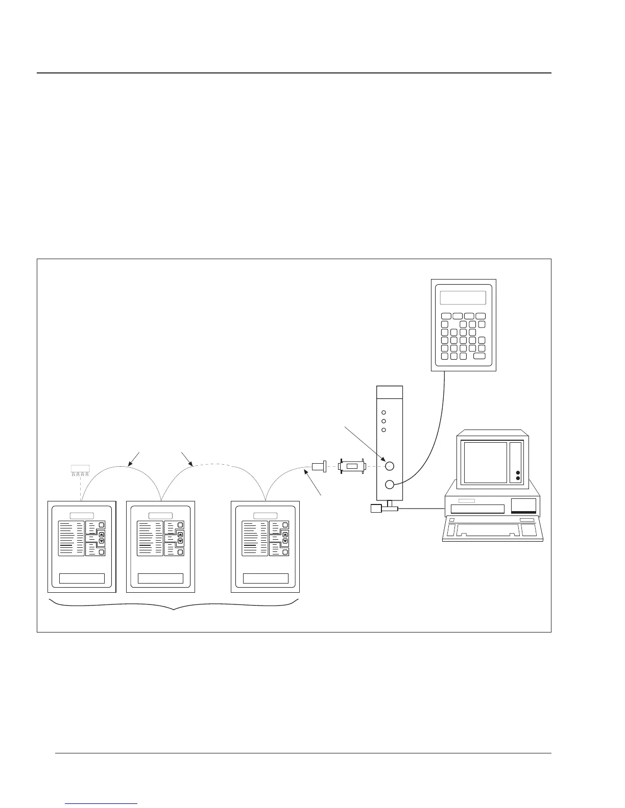
Figure 3-18: POWERLOGIC devices connected to a PNIM
MCA-485
MCT-485
BELDEN 8723
(or equivalent)
CAB-107
(See Appendix D
for cable pinouts)
1–32 Devices (Circuit Monitors and other
POWERLOGIC
-compatible devices)
PNIM
System Display
Remote PC
Connect Circuit Monitors
to top port (port 0) of
PNIM only.
CAB-107
(see Appendix B
for cable pinouts)
 Loading...