Bulletin No. 3020IB9814
December 1998
60
Detailed Setup Procedure This section offers detailed steps on how to set up alarm/relay functions
from the front panel. Figure 4-4 illustrates the general flow of the setup
procedure.
To set up alarm/relay functions, complete the following steps:
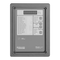
1. Press the MODE button until the red LED next to [Setup] is lit.
The circuit monitor displays “ConFig.”
2. Press the down arrow SELECT METER button until the Circuit
Monitor displays “AL.rLy.”
3. Press the PHASE [Enter] button to select the Alarm/Relay option.
The circuit monitor displays the password prompt “P - - - -.”
4. Enter the master password.
To enter the password, use the SELECT METER [Value] buttons to
increase or decrease the displayed value until it reaches the password
value. Then press the PHASE [Enter] button.
The display alternates between “ALr No” (an abbreviation for alarm
number) and “1”. Appendix I shows that alarm number 1 corresponds to
the alarm condition “Over Current Phase A.” Refer to Alarm Setup
Information in the Circuit Monitor Reference Manual while setting up
alarm/relay functions.
5. Use the SELECT METER [Value] buttons to increase or decrease the
displayed alarm number until you reach the desired number.
The circuit monitor display stops alternating while you change the alarm
number. If an alarm condition is enabled, the circuit monitor displays the
alarm condition’s priority to the left of the alarm number. For example, if
you had previously enabled alarm number 1 and assigned it priority 0,
the circuit monitor would display “P0 1”.
6. Press the PHASE [Enter] button to select the alarm number.
If you have not previously enabled this alarm condition, the display
alternates between “ENAbLE” and “OFF.” If you’ve previously enabled
this alarm condition, the display alternates between “ENAbLE” and the
chosen alarm priority (P0, P1, P2, or P3).
7. To enable the selected alarm condition, and to assign the alarm condition
a priority level, press the down arrow SELECT METER [Value] button
until the desired priority level is displayed.
Note: Using POWERLOGIC software, you can assign one or more of the
following actions for each alarm condition. The circuit monitor performs the
assigned actions each time the alarm condition occurs, no matter what the
priority level.
– Operate one or more relay outputs
– Force data log entries into 1–14 user-defined data log files
– Perform a 4-cycle waveform capture
– Perform a 12-cycle event capture

 Loading...