Chapter 3—Installation
35
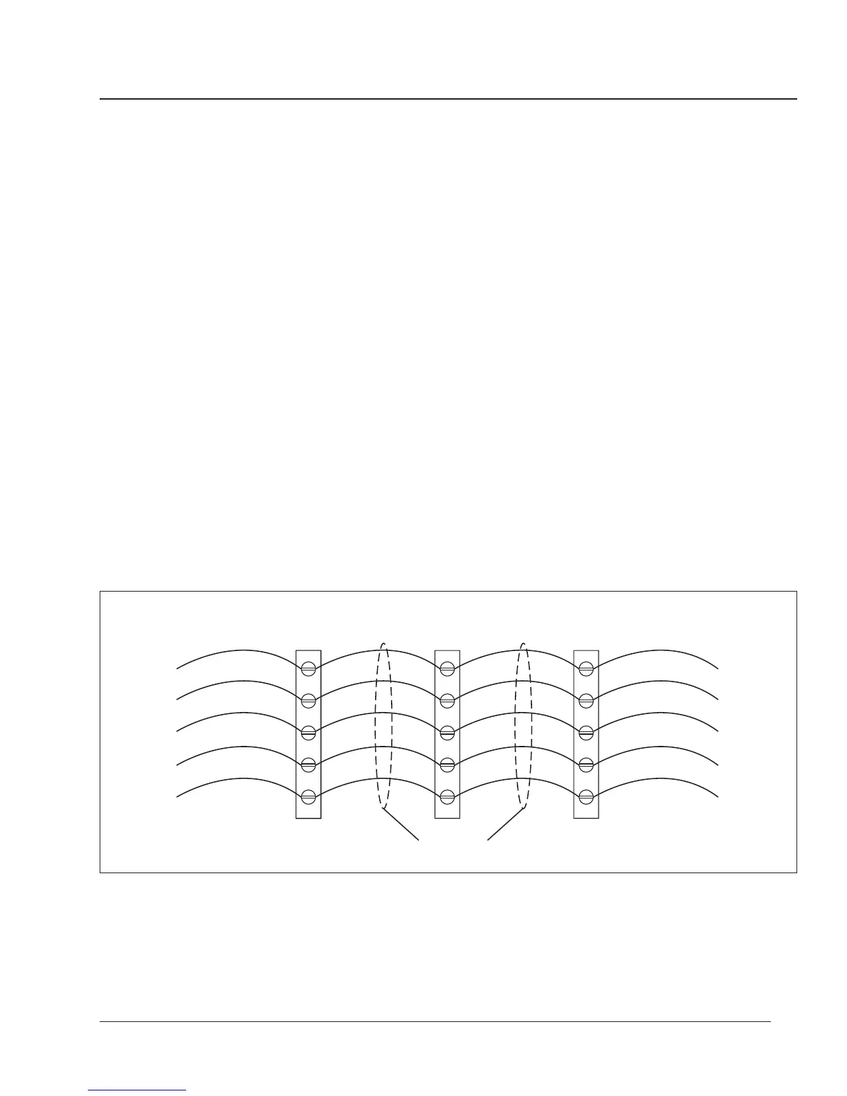
Daisy-Chaining
POWERLOGIC Devices
Note: To daisy-chain POWERLOGIC devices, use communications cable
containing two twisted-shielded pairs (Belden 8723 or equivalent). Connect the
wires to the circuit monitor’s terminals using the red spade connectors included
with the circuit monitor. Using a suitable crimping tool, crimp the red
connectors onto the communications wires.
Each communicating POWERLOGIC device has five RS-485 terminals for
connection to a POWERLOGIC communications link. On all devices, the
terminals are labeled IN+, IN-, OUT+, OUT-, and SHLD. On the circuit
monitor, the IN+, IN-, OUT+, OUT-, and SHLD terminals are numbered 20,
21, 22, 23, and 24, respectively.
To daisy-chain the circuit monitor to another POWERLOGIC device, wire the
circuit monitor’s RS-485 communications terminals to the matching
communications terminals of the next device. In other words, wire the IN+
terminal of the circuit monitor to the IN+ terminal of the next device, wire
IN- to IN-, OUT+ to OUT+, OUT- to OUT-, and SHLD to SHLD.
See Figure 3-20.
If the circuit monitor is the last device on the daisy-chain, terminate it. See
Terminating the Communications Link in this chapter for instructions. If
the circuit monitor is the first device on the daisy-chain, connect it to the
PNIM, personal computer, system display, or programmable controller using
a CAB-107 or equivalent cable and a Multipoint Communications Adapter.
See Biasing the Communications Link in this chapter for instructions. See
Communication Cable Pinouts in the Circuit Monitor Reference Manual for
the CAB-107 pinout.
Figure 3-20: Daisy-chaining the RS-485 communications terminals
IN+
IN-
OUT-
OUT+
SHLD
IN+
IN-
OUT-
OUT+
SHLD
IN+
IN-
OUT-
OUT+
SHLD
Circuit Monitor
or other POWERLOGIC-
compatible Device
Circuit Monitor
or other POWERLOGIC-
compatible Device
Circuit Monitor
or other POWERLOGIC-
compatible Device
To RS-485
Terminals of
next device
To RS-485
Terminals of
next device
Belden 8723
(or equivalent)
Green*
White
Red
Black
* Standard conductor color convention
 Loading...