Chapter 3—Installation
15
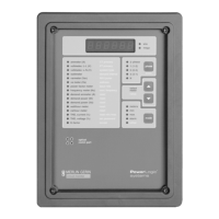
MOUNTING THE CIRCUIT The circuit monitor is a flush-mounted device that projects through the back
MONITOR of a panel or breaker cell door. Table 3-1 lists typical mounting locations in
various power equipment designs.
Note: Series 2000 circuit monitors use the same cutout dimensions and
hole patterns as the Series 100, 200 circuit monitors, but the required rear clearances
have increased.
When choosing a mounting location, consider the following points:
• Allow for easy access to the rear of the circuit monitor.
• Allow extra space for all wires, shorting blocks, or other components.
• Consider the depth of the circuit monitor. Include extra depth for add–on
modules that you might add in the future. See Appendix A for circuit
monitor dimensions.
• Be sure that ambient conditions fall within the acceptable range: operating
temperature –25°C to +70°C, relative humidity, 5–95% non-condensing.
For CE mounting requirements, see CE Compliance, page 14.
Note: Before preparing the cutout, refer to Appendix A and verify that the
required clearances exist.
To mount the circuit monitor, complete the following steps:
1. Prepare the cutout and mounting holes. Refer to figure 3-2 for exact
dimensions.
2. Insert the circuit monitor through the cutout from the front of the panel
or breaker cell door. Guide the circuit monitor mounting studs through
the holes in the panel.
3. Secure the circuit monitor to the panel using four #10-32 hex nuts
included in the circuit monitor hardware kit (63230-204-16). Figure 3-3
shows the circuit monitor mounted in an electrical panel.
Table 3-1
Typical Circuit Monitor Mounting Locations
Equipment Type Mounting Location
QED Switchboards, Model 6 MCCs Main Meter Location or Aux. Section
POWER-ZONE
III Switchgear Main Instrument Compartment Door
HVL and VISI/VAC
Switchgear 9-inch Front Panel or Instrument Door
Metal-Clad and Substation CBs Standard Relaying Locations
ISO-FLEX
Medium Voltage MCCs Standard Relaying Locations
 Loading...