Chapter 3—Installation
17
System Type Sys ID
➀
# CTs Aux. CT # PTs PT Conn. Currents Voltages Figure #
3∅, 3-wire 30 2 None 2 Open Delta A, B
➁
, C A-B, B-C, C-A
➁
3-4
Delta
3∅, 4-wire 40 3 None 3 Wye-Wye A, B, C, N
➁
A-N, B-N, C-N 3-5
Wye, Ground A-B
➁
, B-C
➁
, C-A
➁
3∅, 4-wire 41 3 Neut 3 Wye-Wye A, B, C, N, G
➁
A-N, B-N, C-N 3-6
Wye, Ground A-B
➁
, B-C
➁
, C-A
➁
3∅, 4-wire 40 2 None 3 Wye-Wye A, B, C, N
➁
A-N, B-N, C-N 3-7
Wye, Ground
➂
A-B
➁
, B-C
➁
, C-A
➁
3∅, 4-wire 42 3 None 2 Open Wye A, B, C, N
➁
A-N, B-N
➁
, C-N 3-8
Wye, Ground A-B
➁
, B-C
➁
, C-A
➁
3∅, 4-wire 43 3 Neut 2 Open Wye A, B, C, N, G
➁
A-N, B-N
➁
, C-N 3-9
Wye, Ground A-B
➁
, B-C
➁
, C-A
➁
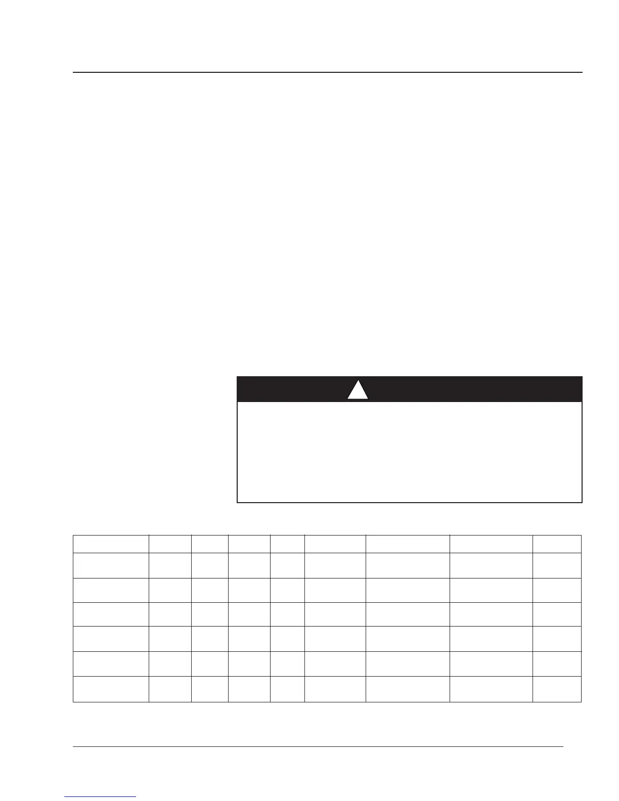
WIRING CTs, PTs, AND The circuit monitor supports a variety of 3-phase power system wiring
CONTROL POWER connections, including 3-wire delta, and 4-wire wye. Table 3-2 lists the
supported system connections. Figures 3-4 through 3-9 show CT, PT, and
control power wiring. Figure 3-10 on page 24 shows dc control power.
Notes:
• When wiring the circuit monitor, route wires outward to make room for
add-on modules that you might install in the future.
• Wiring instructions are also included in CM hardware kit.
• For CE wiring requirements, see CE Compliance, page 14.
To wire the circuit monitor, complete the following steps:
1. Using a suitable crimping tool, crimp the blue spade connectors included
with the circuit monitor onto the wires for the voltage, current, and
control power inputs.
2.
Connect the spade connectors to the circuit monitor terminals as shown in
the appropriate wiring diagram. (Figures 3-4 through 3-10 show wiring
connections.) Do not overtighten screws, but ensure that they are snug.
3. Ground the circuit monitor. See Grounding the Circuit Monitor in this
chapter for instructions.
4. Install protective terminal strip covers. See Appendix C for instructions.
DANGER
!
HAZARD OF PERSONAL INJURY OR DEATH
Only qualified electrical workers should install and wire this equipment.
Such work should be performed only after reading this complete set of
instructions. Follow proper safety procedures regarding CT secondary
wiring. Never open circuit the secondary of a CT.
Failure to observe this precaution will result in death, serious injury
or equipment damage.
Table 3-2
Supported System Wiring Connections
➀ The System ID is used during setup to specify the system type.
➁ Indicates a value that is calculated rather than measured directly.
➂ For 3-wire loads only.
 Loading...