Bulletin No. 3020IB9814
December 1998
42
CONFIGURING THE This section tells how to use the Configuration option to define the following
CIRCUIT MONITOR values: CT and PT ratios, system type, demand interval, WH/pulse output,
device address, baud rate, nominal frequency, and password. It also tells
how to reset energy, demand and min/max values.
The section General Configuration Procedure describes the general steps
required to configure the circuit monitor. The remaining sections tell how to
configure specific values.
Factory Defaults Table 4-1 lists the front panel configuration parameters, their allowed values,
and their factory defaults.
Table 4-1
Factory Defaults for Front Panel Configuration Parameters
Parameter Allowed Values Default
CT Primary
Primary, 3-Phase 1 to 32,767 5
Primary, Neutral 1 to 32,767 5
PT Primary
Primary, 3-Phase 1 to 1,700,000 120
System Type 30, 40, 41 40
Demand Interval 5 to 60 min. 15
WH/Pulse output 0 to 3276.7 kWH 0
Device Address 0 to 199 1
Baud Rate 1,200–19,200 9,600
Frequency (Nom.) 50, 60, 400 60
Password 0 to 9998 0
General Configuration This section describes the general steps required to configure the circuit
Procedure monitor from the front panel. The configuration items (and reset items) are
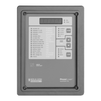
the grey items in square brackets on the front panel of the circuit monitor.
Refer to these items when configuring the circuit monitor.
The front panel configuration procedure is described below. Alternately,
figure 4-2 on page 44 shows the configuration procedure, with less detail, as
a flow chart.
To configure the circuit monitor, complete the following steps:
1. Press the MODE button until the red LED next to [Setup] is lit.
The circuit monitor displays “ConFig”.
2. Press the PHASE [Enter] button to select the Configuration option.
The circuit monitor displays the password prompt “P - - - -.”
 Loading...