Bulletin No. 3020IB9814
December 1998
52
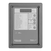
Setting the Device Each POWERLOGIC device on a communications link must have a
Address unique device address. (The term communications link refers to 1-32
POWERLOGIC compatible devices daisy-chained to a single
communications port.) The allowable range of addresses is 1 to 198. The
factory default address is 1. (The circuit monitor will actually accept address
199, but address 199 is a special reserved address and we recommend that
you not use it.)
Note: By networking groups of devices, POWERLOGIC systems can support a
virtually unlimited number of devices.
When addressing POWERLOGIC devices, remember the following points:
• Each device on a single communications link—including the PNIM or
SY/LINK card—must be assigned a unique address.
• Normally, the last device on a communications link—the device farthest
from the communications port—should be assigned device address 1.
• If a communications link has only a single device, assign it address 1.
• If you add devices to the communications link, the last device should
retain the address 1.
To change the device address, complete the following steps:
1. Press the MODE button until the red LED next to [Setup] is lit.
The circuit monitor displays “ConFig.”
2. Press the PHASE [Enter] button to select the Configuration option.
The circuit monitor displays the password prompt “P - - - -.”
3. Enter the password.
To enter the password, use the SELECT METER [Value] buttons to
increase or decrease the displayed value until it reaches the password
value. Then press the PHASE [Enter] button.
4. Press the PHASE [Enter] button until the red LED next to
[Address] flashes.
5. Press the SELECT METER [Value] buttons until the desired address is
displayed.
6. Press the MODE button once.
The red LED next to [Accept] flashes. The red LED next to [Address]
glows steadily.
7. To reject the new address, press the PHASE [Enter] button once.
The circuit monitor returns to METERS mode.
8. To accept the new address, press the SELECT METER [Value] button to
change from No to Yes. Then, press the PHASE [Enter] button.
The circuit monitor restarts.
 Loading...