Chapter 3—Installation
27
(+)L G N(-)
IN+ IN- OUT+ OUT- SHLD
20 21 22 23 24
910111256781234
V
a
V
b
V
c
V
n
I
a+
I
a-
I
b+
I
b-
I
c+
I
c-
I
n+
I
n-
25 26 27
3 PHASE
VOLTAGE
INPUTS
120 VOLTS
NOMINAL
AUXILIARY
CURRENT
INPUTS
5 AMPS
NOMINAL
3 PHASE
CURRENT
INPUTS
5 AMPS
NOMINAL
CONTROL
POWER
RS-485
DATA COMMUNICATIONS
TYPE 1 ENCLOSURE
INDOOR USE ONLY
(+)L G N(-)
IN+ IN- OUT+ OUT- SHLD
20 21 22 23 24
910111256781234
V
aVbVcVnIa+Ia-Ib+Ib-Ic+Ic-In+In-
25 26 27
3 PHASE
VOLTAGE
INPUTS
120 VOLTS
NOMINAL
AUXILIARY
CURRENT
INPUTS
5 AMPS
NOMINAL
3 PHASE
CURRENT
INPUTS
5 AMPS
NOMINAL
CONTROL
POWER
RS-485
DATA COMMUNICATIONS
TYPE 1 ENCLOSURE
INDOOR USE ONLY
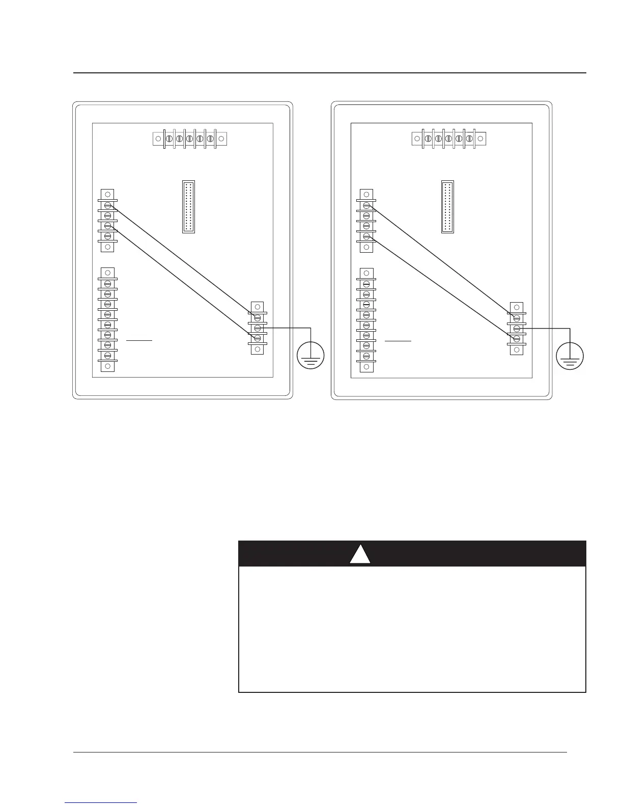
Figure 3-12: Deriving L-L control power from phase PT inputs Figure 3-13: Deriving L-N control power from phase PT inputs
GROUNDING THE For optimal grounding, connect the circuit monitor to a true earth ground.
CIRCUIT MONITOR
To ground the circuit monitor, complete the following steps:
1. Connect the Ground terminal (terminal 26) to a true earth ground, using
#14 AWG wire or larger with spade connector (see figure 3-14).
2. Install protective terminal strip cover. See Appendix C for instructions.
HAZARD OF ELECTRIC SHOCK
Ground the circuit monitor as described in these instructions. Failure
to properly ground the circuit monitor may allow hazardous voltages
to be present on the circuit monitor chassis, and may result in
equipment damage.
Failure to observe this precaution will result in death, serious
injury or equipment damage.
DANGER
!
 Loading...