Bulletin No. 3020IB9814
December 1998
36
Terminating the To ensure reliable communications, terminate the last device on a
Communications Link POWERLOGIC communications link. To terminate the last device, use a
POWERLOGIC Multipoint Communications Terminator (Class 3090 Type
MCT-485).
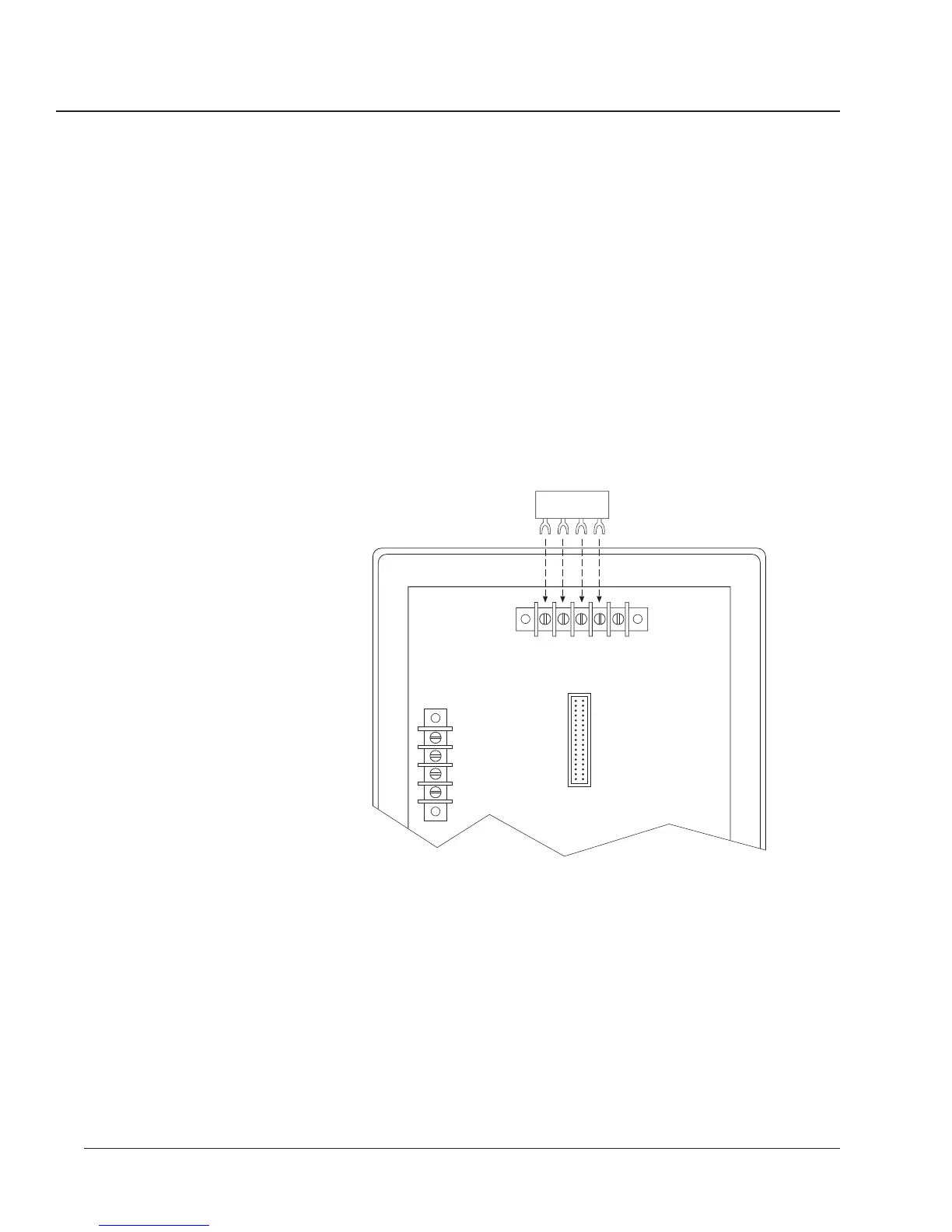
To terminate a circuit monitor, slide the terminator’s four spade connectors
under the IN+, IN-, OUT+, and OUT- terminals on the back of the circuit
monitor and tighten. Figure 3-20 shows proper placement of the terminator.
Figures 3-15 to 3-19 show the terminator applied in typical systems.
Notes:
• Terminate only the last device on the link. If a link has only one device,
terminate that device.
• Some POWERLOGIC devices use a removable communications connector. If
the last device on the communications link is not a circuit monitor, refer to
the instruction bulletin for that device for termination instructions.
IN+ IN- OUT+ OUT- SHLD
20 21 22 23 24
9101112
V
a
V
b
V
c
V
n
3 PHASE
VOLTAGE
INPUTS
120 VOLTS
NOMINAL
RS-485
DATA COMMUNICATIONS
TYPE 1 ENCLOSURE
INDOOR USE ONLY
Figure 3-21: Terminator placement when last device on the link
is a circuit monitor
 Loading...