Chapter 2—Hardware Description
11
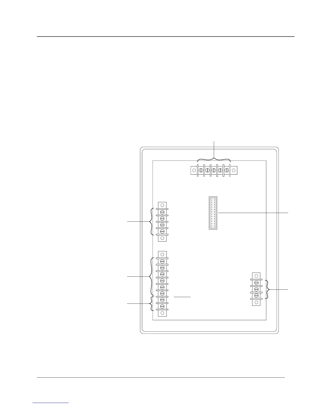
REAR CONNECTIONS Figure 2-2 shows the rear of the circuit monitor. Identified parts are as
follows:
➀ Auxiliary Current Inputs
➁ 3-Phase Current Inputs
➂ 3-Phase Voltage Inputs
➃ RS-485 Communications Terminals
➄ Input/Output Module Connector
➅ Control Power Terminals
Note: See Chapter 3—Installation for wiring instructions.
Figure 2-2: Back of the circuit monitor
(+)L G N(-)
IN+ IN- OUT+ OUT- SHLD
20 21 22 23 24
910111256781234
V
a
V
b
V
c
V
n
I
a+
I
a-
I
b+
I
b-
I
c+
I
c-
I
n+
I
n-
25 26 27
3 PHASE
VOLTAGE
INPUTS
120 VOLTS
NOMINAL
AUXILIARY
CURRENT
INPUTS
5 AMPS
NOMINAL
3 PHASE
CURRENT
INPUTS
5 AMPS
NOMINAL
CONTROL
POWER
RS-485
DATA COMMUNICATIONS
TYPE 1 ENCLOSURE
INDOOR USE ONLY
➅
➄
➀
➁
➂
➃
 Loading...