Bulletin No. 3020IB9814
December 1998
ii
Configuring the Circuit Monitor ......................................................................................................................... 42
Factory Defaults ............................................................................................................................................. 42
General Configuration Procedure ............................................................................................................... 42
Viewing Configuration Data in Protected Mode ...................................................................................... 45
Setting the Master Password........................................................................................................................ 46
Configuring the Circuit Monitor (cont.)
Setting the CT Ratios ..................................................................................................................................... 47
Setting the PT Ratio ....................................................................................................................................... 48
Setting the System Type ............................................................................................................................... 48
Setting the Demand Interval ........................................................................................................................ 49
Setting the Watthour/Pulse Output ........................................................................................................... 51
Setting the Device Address .......................................................................................................................... 52
Setting the Baud Rate .................................................................................................................................... 53
Setting the Nominal Frequency ................................................................................................................... 54
Resetting Demand, Energy, and Min/Max Values .................................................................................. 55
Performing Resets Using the Resets Option ...................................................................................................... 56
Setting Up Alarm/Relay Functions .................................................................................................................... 58
General Setup Procedure .............................................................................................................................. 59
Detailed Setup Procedure............................................................................................................................. 60
Viewing Active Alarms ........................................................................................................................................ 63
Viewing the Priority 1 Log ................................................................................................................................... 64
Clearing the Priority 1 Log ................................................................................................................................... 65
CHAPTER 5—MAINTENANCE AND TROUBLESHOOTING ......................................................................67
Maintenance ........................................................................................................................................................... 67
Battery-Backed RAM..................................................................................................................................... 67
Troubleshooting..................................................................................................................................................... 68
Getting Technical Support ................................................................................................................................... 69
APPENDICES
Appendix A—Circuit Monitor Dimensions ...................................................................................................... 71
Appendix B—Specifications ................................................................................................................................ 73
Appendix C—Installing Terminal Strip Covers ............................................................................................... 75
FIGURES
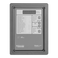
2-1 Circuit monitor front panel ...................................................................................................................... 10
2-2 Back of the circuit monitor ....................................................................................................................... 11
3-1 Example of disconnect breaker for CE compliance ..............................................................................14
3-2 Panel preparation ...................................................................................................................................... 16
3-3 Circuit monitor mounted in electrical panel ......................................................................................... 16
3-4 3-phase, 3-wire delta connection ............................................................................................................. 18
3-5 3-phase, 4-wire wye, ground connection ............................................................................................... 19
3-6 3-phase, 4-wire wye, ground connection, metered neutral ................................................................. 20
3-7 3-phase, 4-wire wye, 3-wire load ............................................................................................................ 21
3-8 2-1/2 element metering system type 42 (calculated neutral).............................................................. 22
3-9 2-1/2 element metering system type 43 ................................................................................................. 23
 Loading...