PAGE 20 Metor 6M
Installation and Operating Manual
6. ASSEMBLY 92102916 REV 5
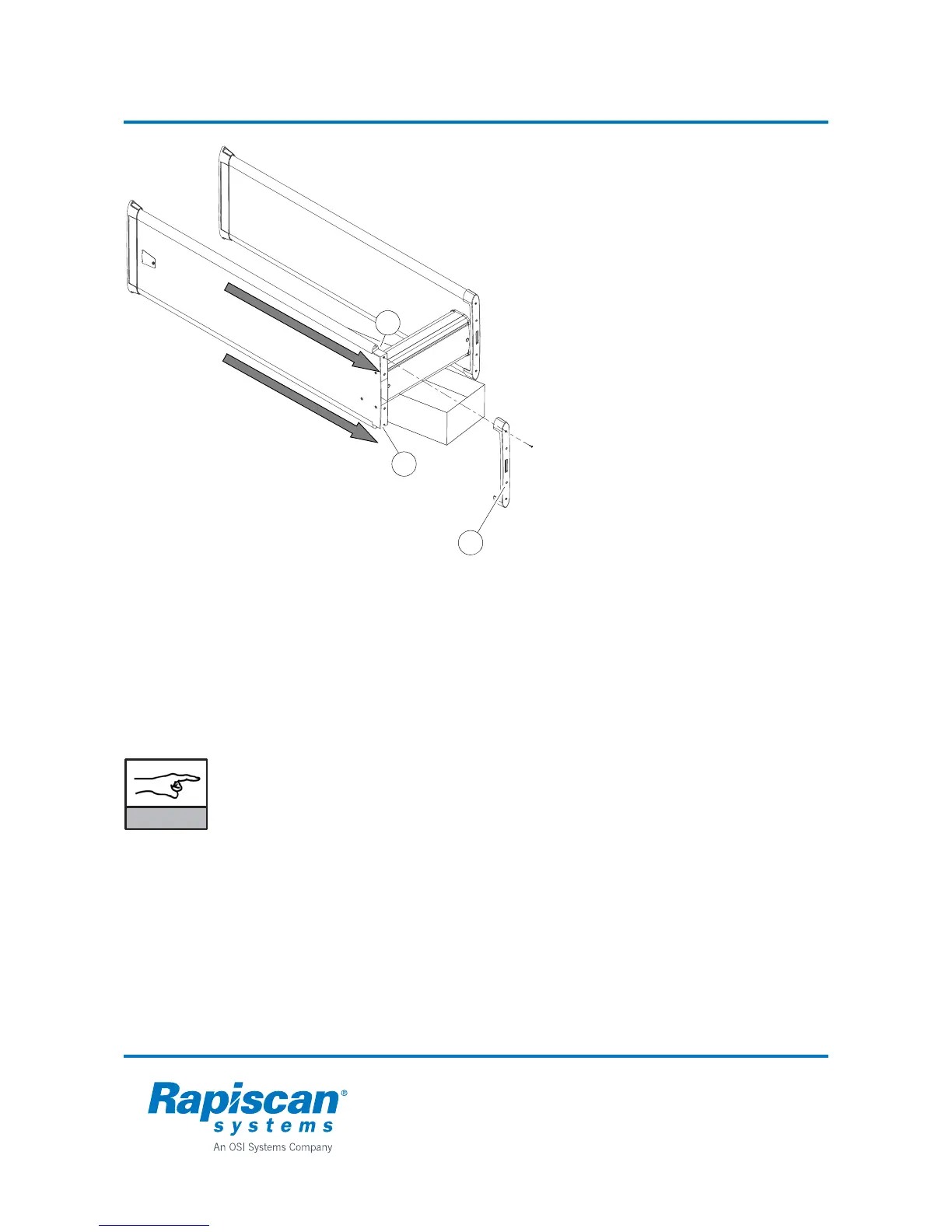
Changing the position of the zone
display:
If necessary the zone display can be
moved to the opposite side of the coil
panel.
1. Lay the Metor 6M down. Place a support
under the cross piece so that only the
coil panel bottoms touch the ground
(e.g. the cardboard package the cross
piece came in)
2. Detach the top piece (1) which is held in
position by four screws.
3. Detach the zone display cable (2) and
the counter TX cable (3) from the top of
the tubes.
4. DO NOT remove the green and red
cables on top of the panel. DO NOT
switch the positions of the cables.
5. Gently slide out the zone display and
counter TX tubes to the direction
indicated.
6. Slide the tubes gently in on the opposite
sides of the coil panels.
7. Reconnect the cables in corresponding
connectors. Check that connectors lock
in position.
8. Re-install the top piece and fasten it with
the four screws.
NOTICE
When changing the side of zone display or adding a second zone display you need
to select correct zone display mode from user interface, menu "2.4.1 ZONES", refer
to chapter 10 for further information.
DO NOT try to change zone display to RX panel as such action will cause a fault
situation.
If you want to add a second zone display to TX panel simply remove counter tube
and replace it with a second zone display.
1
2
3