PAGE 22 Metor 6M
Installation and Operating Manual
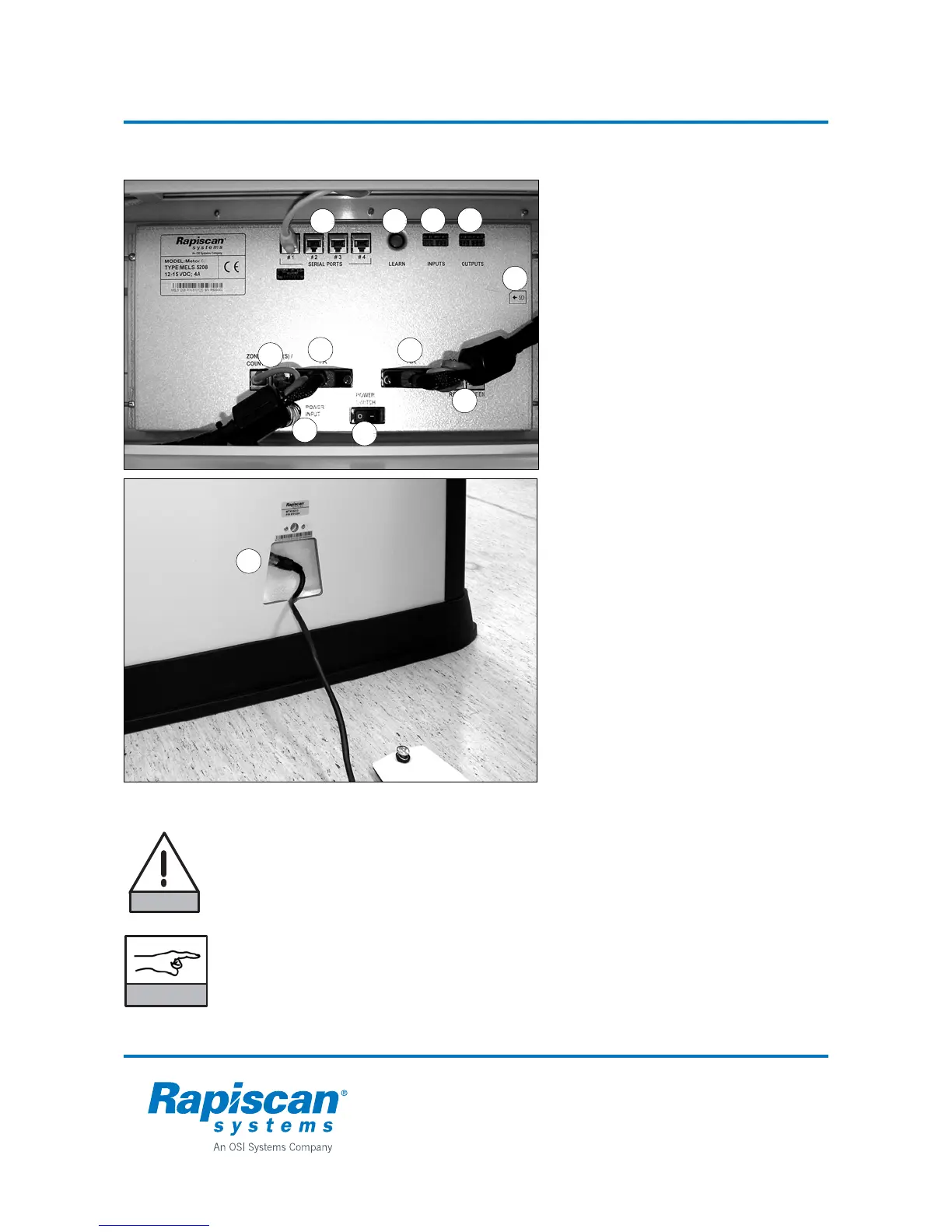
6. ASSEMBLY 92102916 REV 5
Electrical connections
Connections
1. Tx panel connector
2. Rx panel connector
3. Zone display / Counter Tx connector
(2 pcs)
4. Counter Rx connectors (2 pcs)
5. Serial port connections (4 pcs),
all similar
• Display
• Traffic lights (option)
• MetorNet (option)
6. Relay outputs (2 pcs)
7. Digital inputs (2 pcs)
8. Power input connector
9. Memory card slot
10.Power supply connection cable
Switches
11.LEARN button for Remote Control Unit
12.Power switch
Electrical assembly
• Connect Tx and Rx cables to the
electronics.
• Connect the display and traffic lights
(option) cable to any of the serial ports.
• Connect DC power cable to the
electronics.
• Connect power supply to Tx panel.
Connect power cord to electric wall
socket.
• Turn the power switch on.
• Close the lid.
DANGER
Manufacturer supplied power supply must be used. Do not connect any other
power supply to the DC power cable.
Power supply shall be located as to be easily accessible for disconnection.
NOTICE
Do not change DC power cable to RX panel as it may produce interference to
the unit.
Do not force the connections to avoid damaging the contacts.
7 6
5
4
8
2
9
1
3
12
11
10