Table of figures
■■■■■■■■■■■■■■■■■■■■■■
VI
■■■■■■■■
883 Basic IC plus
Table of figures
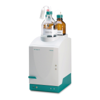
Figure 1 883 Basic IC plus front ....................................................................... 6
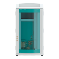
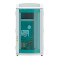
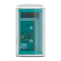
Figure 2 883 Basic IC plus rear ........................................................................ 7
Figure 3 Installation diagram 883 Basic IC plus .............................................. 12
Figure 4 Positioning the detector .................................................................. 17
Figure 5 Drainage tubing .............................................................................. 20
Figure 6 Capillary feed-throughs on the door ................................................ 22
Figure 7 Installing the eluent bottle cap ........................................................ 23
Figure 8 Installing tubing weighting and aspiration filter ................................ 25
Figure 9 High-pressure pump with purge valve .............................................. 27
Figure 10 Inline filter ....................................................................................... 28
Figure 11 Pulsation absorber ........................................................................... 28
Figure 12 Exchanging the sample loop ............................................................ 30
Figure 13 Suppressor – Connection capillaries ................................................. 34
Figure 14 Peristaltic pump ............................................................................... 42
Figure 15 Front of conductivity detector ......................................................... 43
Figure 16 Rear of conductivity detector ........................................................... 44
Figure 17 Connection detector–MSM ............................................................. 45
Figure 18 High-pressure pump – Parts ............................................................. 60
Figure 19 High-pressure pump – Cross-section ................................................ 67
Figure 20 Tool for piston seal (6.2617.010) ..................................................... 67
Figure 21 Removing the piston cartridge from the pump head ........................ 68
Figure 22 Inserting the piston seal into the tool ............................................... 69
Figure 23 Parts of the piston cartridge ............................................................ 70
Figure 24 Inline filter – Removing the filter ...................................................... 74
Figure 25 Parts of the suppressor .................................................................... 77
Figure 26 Pump tubing connection – Replacing the filter ................................. 85