Page 102
8.10 Connection: CAN-Bus [X4]
8.10.1 Device side [X4]
D-SUB connector, 9-pole, male
8.10.2 Counterplug [X4]
D-SUB connector, 9-pole, female
Housing for 9-pole D-SUB connector with bolting screws 4/40 UNC
8.10.3 Pin assignment [X4]
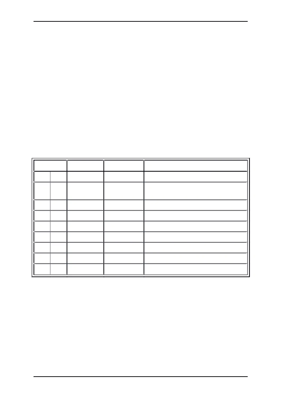
Table 40: Pin assignment: CAN-Bus [X4]
Pin No Denomination Values Specification
1 Not occupied
6 GND 0 V CAN-GND, galvanically connected to GND in
servo drive
2 CANL
*)
CAN-Low signal line
7 CANH
*)
CAN-High signal line
3 GND 0 V See Pin no. 6
8 Not occupied
4 Not occupied
9 Not occupied
5 Shield PE Connection for cable shield
*)
For terminating the CAN bus on both ends, an integrated 120 Ohm resistor is provided and can be switched on
with the CAN Term switch at the ARS 2000 SE front.
Product Manual „Servo drives ARS 2100 SE“ Version 5.0
 Loading...

