Page 36
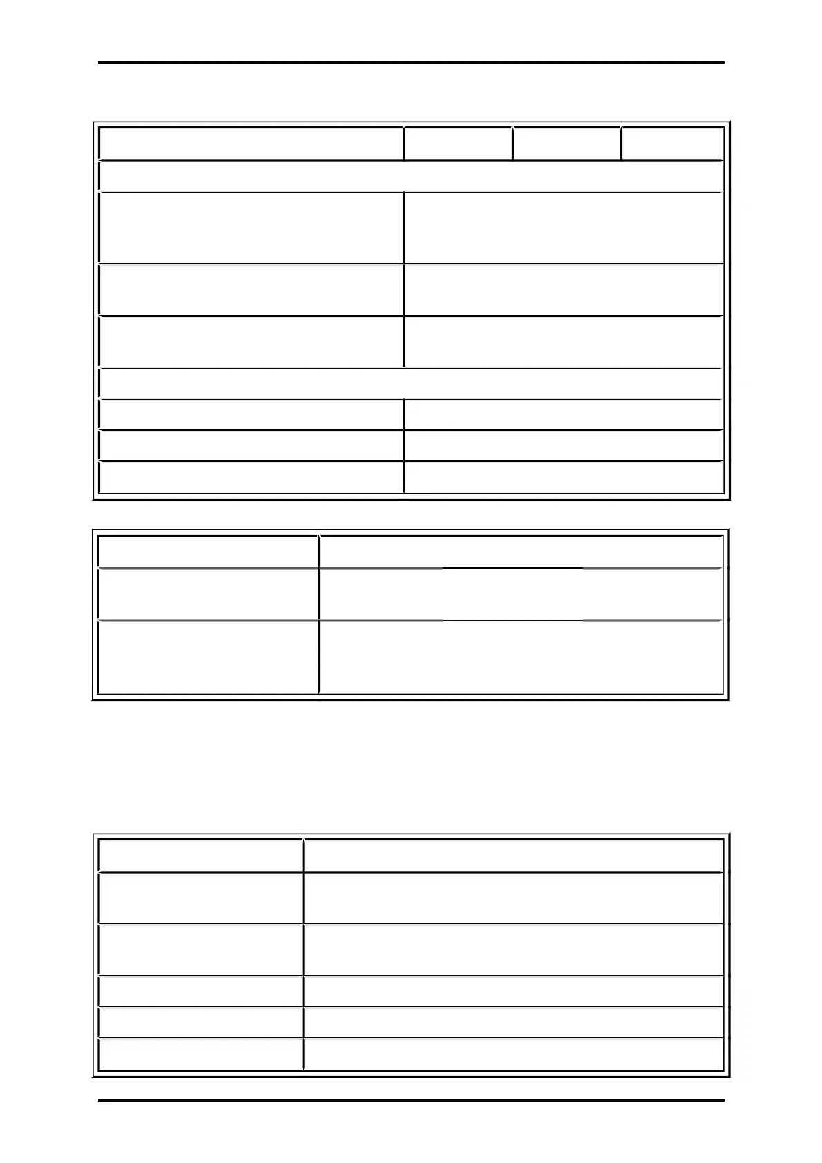
Table 8: Technical data: Cable specifications
Range ARS 2102 SE ARS 2105 SE ARS 2108 SE
Maximum motor cable length for interference emission as per EN 61800-3 for f
PWM
10 kHz
Category C2
Switch cabinet assembly (see chapter 8.14
Notes on safe and EMC-compliant installation)
l 25 m
Category C3
(industrial area)
l 25 m
Cable capacity of a phase against shield or
between two lines
C‘ 200 pF/m
Derating of the cable length (see also chapter 8.14.5 Operation with long motor cables)
f
PWM
= 12 kHz
l 21 m
f
PWM
= 16 kHz
l 15 m
f
PWM
= 20 kHz
l 12 m
Table 9: Technical data: Motor temperature monitoring
Motor temperature monitoring Values
Digital sensor Normally closed
contact:
R
cold
< 500 R
hot
> 100 k
Analogue sensor Silicon temperature sensor, for example KTY81, 82 or similar
R
25
2000
R
100
3400
4.2 Operating and display elements
On the front the ARS 2100 SE series servo drives have two LEDs and one seven-segment display to
indicate the operating status.
Table 10: Display elements and RESET button
Element Function
Seven segment display Display of operating mode and a coded error number in the case
of a malfunction
LED 1
(two-colour LED, green/red)
Operational state respectively error
LED 2 (green) Servo drive enable
LED 3 (yellow) Status display CAN-Bus
RESET button Hardware reset for processor
Product Manual „Servo drives ARS 2100 SE“ Version 5.0
 Loading...

