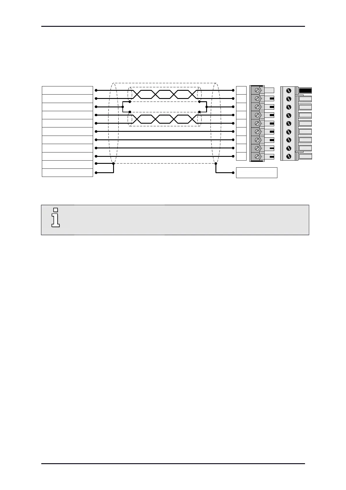
Figure 15: Motor connection [X6]
ARS 2102 SE and ARS 2105 SE:
ARS 2108 SE:
PHOENIX MINI-COMBICON MC 1,5/ 9-ST-5,08 BK
PHOENIX COMBICON MSTB 2,5/9-ST-5,08 BK
Connect the inner shields to Pin 3; maximum length 40 mm
Maximum length of unshielded cores 35 mm
Connect total shield on the servo drive flat to PE terminal; maximum length 40 mm.
Connect total shield on motor side flat to connector or motor housing; maximum length 40 mm
Via terminals ZK+ and ZK- the DC buses of several ARS 2100 SE series servo drives can be
interconnected. The coupling of the DC bus is interesting for applications with high brake energies or if
movements have to be carried out even in the case of power failure.
A holding brake can be connected to the terminals BR+ and BR- of the motor. The holding brake is fed
by the servo drive’s power supply. Note the maximum output current provided by the servo drive. A
relay may have to be placed between the device and the holding brake as shown in Figure 16:
Product Manual „Servo drives ARS 2100 SE“ Version 5.0
 Loading...

