Page 80
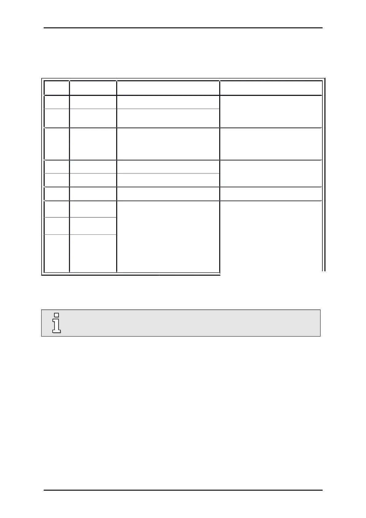
8.4.3 Pin assignment [X6]
Table 32: Pin assignment: [X6]
Pin No Denomination Values Specification
1 BR- 0 V brake Holding brake (motor), signal level
dependent on switch status, high
side / low side switch
2 BR+ 24 V brake
3 PE PE Connection for inner shield
(holding brake + temperature
sensor)
4 MT- GND
Motor temperature sensor
1)
, N.C.
and N.O. contact, PTC, NTC, KTY
5 MT+ + 3,3 V / 5 mA
6 PE PE Motor ground conductor
7 W 0 ... 230 V
RMS
0 ... 2,5 A
RMS
0 ... 5 A
RMS
0 ... 8 A
RMS
0 ... 1000 Hz
ARS 2102 SE
ARS 2105 SE
ARS 2108 SE
Connection of the three motor
phases
8 V
9 U
1)
Please comply with Chapter 9 Additional requirements for the servo drives concerning the UL approval on
page 113.
The cable shield of the motor cable must also be connected to the servo drive housing
(PE screw terminal).
Product Manual „Servo drives ARS 2100 SE“ Version 5.0
 Loading...


