Home
Metronix
Servo Drives
ARS 2100 SE Series
Metronix ARS 2100 SE Series User Manual
4
of 1
of 1 rating
156 pages
Give review
Manual
Specs
To Next Page
To Next Page
To Previous Page
To Previous Page
Loading...
Page 85
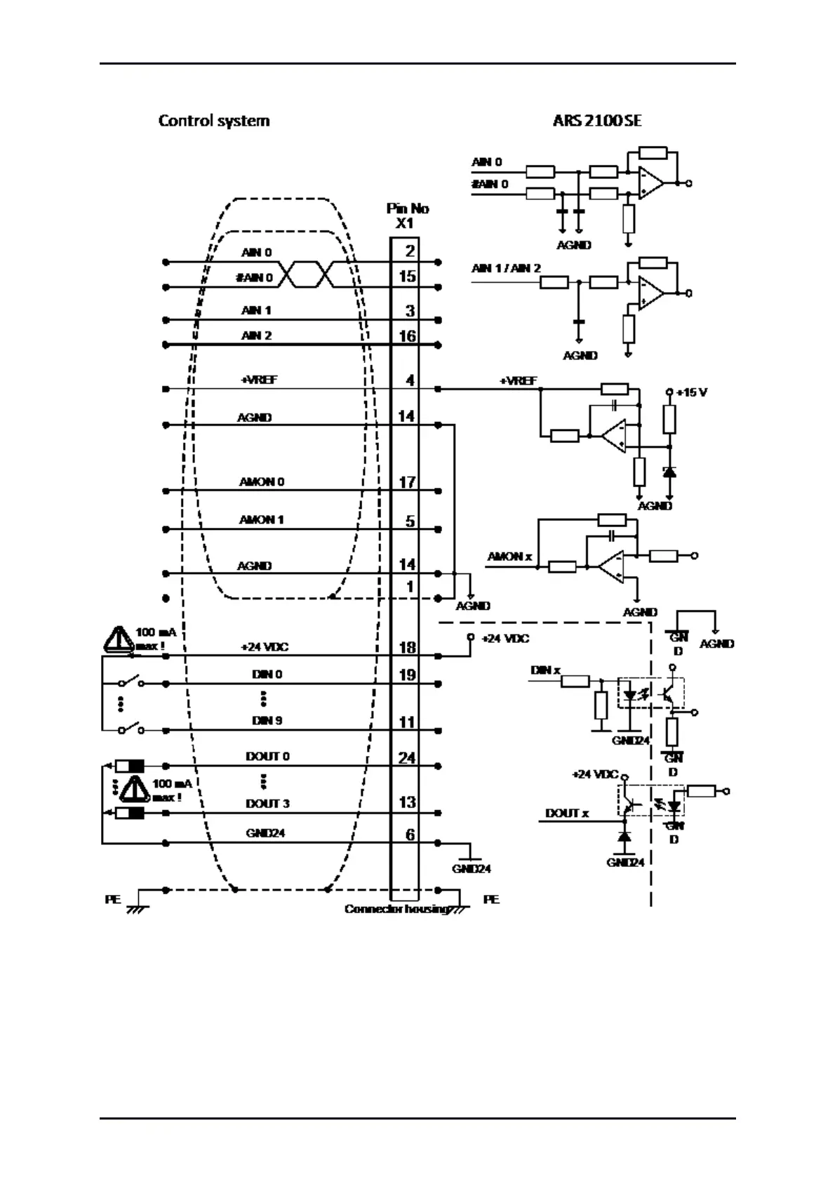
Figure 17:
Basic circuit diagram connector [X1]
The servo drive
ARS 2100 SE comprises one dif
ferential (AIN
0) and two single-ended analogue
inputs, designed for input voltages within a rang
e of
10V
. The inputs
AIN 0 and #AIN
0 are lead to the
control via twisted cables (twisted pair design).
Product Manual „Servo drives
ARS
2100 SE“
V
e
rsion 5.0
84
86
Table of Contents
Default Chapter
4
Table of Contents
4
1 General
12
Documentation
12
Scope of Supply
13
Table 1: Scope of Supply ARS 2100 SE with STO
13
Table 2: Scope of Supply ARS 2100 SE Without STO
13
Table 3: Connector Set: POWER Connector
13
2 Safety Notes for Electrical Drives and Controllers
15
Used Symbols
15
General Notes
16
Danger Resulting from Misuse
18
Safety Notes
19
General Safety Notes
19
Safety Notes for Assembly and Maintenance
21
Protection against Contact with Electrical Parts
23
Protection against Electrical Shock by Means of Protective Extra-Low Voltage (PELV)
24
Protection against Dangerous Movements
25
Protection against Contact with Hot Parts
26
Protection During Handling and Assembly
27
3 Product Description
28
General
28
Figure 1: Type Key
28
Power Supply
31
Single-Phase AC Supply
31
DC Bus Coupling, DC Supply
32
Mains Fuse
32
Brake Chopper
32
Communication Interfaces
33
USB Interface [X19]
33
UDP Interface [X18]
34
CAN Interface [X4]
34
I/O Functions and Device Control
34
4 Technical Data
35
General Technical Data
35
Table 6: Technical Data: Ambient Conditions and Qualification
35
Table 7: Technical Data: Dimensions and Weight
35
Operating and Display Elements
36
Table 8: Technical Data: Cable Specifications
36
Table 9: Technical Data: Motor Temperature Monitoring
36
Table 10: Display Elements and RESET Button
36
Supply [X9]
37
Table 11: Technical Data: Performance Data [X9]
37
Table 12: Technical Data: Internal Brake Resistor [X9]
37
Table 13: Technical Data: External Brake Resistor [X9]
37
Motor Connection [X6]
38
Current Derating
38
Table 14: Technical Data: Motor Connection [X6]
38
Table 15: ARS 2102 SE: Rated Current for an Ambient Temperature of 40 °C
40
Table 16: ARS 2105 SE: Rated Current for an Ambient Temperature of 40 °C
40
Table 17: ARS 2108 SE: Rated Current for Blocked or Slowly Rotated Motor
41
Table 18: ARS 2108 SE: Rated Current for Rotated Motor (F 3 Hz) and for an Ambient Temperature of 40 °C
42
Motor Feedback Connection [X2A] and [X2B]
43
Resolver Connection [X2A]
43
Encoder Connection [X2B]
44
Table 20: Technical Data: Resolver Interface [X2A]
44
Table 21: Technical Data: Encoder Evaluation [X2B]
44
Communication Interfaces
47
Usb [X19]
47
Ethernet [X18]
47
CAN-Bus [X4]
47
SD-/SDHC-/MMC-Card
47
Table 22: Technical Data: USB [X19]
47
Table 23: Technical Data: Ethernet [X18]
47
Table 24: Technical Data: CAN-Bus [X4]
47
Table 25: Technical Data: SD-/SDHC-/MMC-Card
47
I/O Interface [X1]
48
Incremental Encoder Input [X10]
49
Table 27: Technical Data: Analogue Inputs and Outputs [X1]
49
Table 28: Technical Data: Incremental Encoder Input [X10]
49
Incremental Encoder Output [X11]
50
Table 29: Technical Data: Incremental Encoder Output [X11]
50
5 Function Overview
51
Motors
51
Synchronous Servo Motors
51
Linear Motors
51
Functions of the ARS 2100 SE Series Servo Drives
52
Compatibility
52
Pulse Width Modulation (PWM)
52
Table 30: Output Voltage at the Motor Terminals in the Case of a DC Bus Circuit Voltage
53
Set Point Management
54
Torque-Controlled Mode
54
Speed-Controlled Mode
54
Torque-Limited Speed Control
55
Synchronization to the External Clock Signal
55
Load Torque Compensation for Vertical Axes
55
Positioning and Position Control
56
Synchronisation, Electronic Gearing
56
Brake Management
56
Contouring Control with Linear Interpolation
57
Time-Synchronized Multi-Axis Positioning
57
Figure 3: Linear Interpolation between Two Data Values
57
Electronic Cam Disk
59
Positioning Mode
60
Overview
60
Relative Positioning
61
Absolute Positioning
61
Driving Profile Generator
61
Figure 4: Driving Profiles of the Servo Drive ARS 2100 SE
61
Homing
62
Positioning Sequences (Path Program)
62
Figure 5: Path Program
62
Optional Stop Input
63
Jogging Mode and Teach-In Mode
63
6 Functional Safety Technology
64
General
64
Description of the Integrated Safety Function STO
64
Figure 6: Schematic Representation of the Integrated Safety Function STO
65
7 Mechanical Installation
66
Important Notes
66
Installation Free Space and Mounting Distance
67
Figure 7: Servo Drives ARS 2100 SE with and Without STO: Installation Free Space and Mounting Distance
67
View of the Device
68
Figure 8: Servo Drive ARS 2102 SE: Front View
68
Figure 9: Servo Drive ARS 2102 SE: Top View
70
Figure 10: Servo Drive ARS 2102 SE: Bottom View
70
Mounting
71
Figure 11: Servo Drive ARS 2100 SE: Mounting Plate
71
8 Electrical Installation
72
Connector Configuration
72
ARS 2100 SE Complete System
74
Figure 13: Complete Setup of the ARS 2100 SE (Example with STO) with Motor and PC
75
Connection: Power Supply [X9]
76
Device Side [X9]
76
Counterplug [X9]
76
Pin Assignment [X9]
77
Cable Type and Design [X9]
77
Table 31: Pin Assignment: [X9]
77
Connection Notes [X9]
78
Connection: Motor [X6]
79
Device Side [X6]
79
Counterplug [X6]
79
Pin Assignment [X6]
80
Table 32: Pin Assignment: [X6]
80
Cable Type and Design [X6]
81
Connection Notes [X6]
82
Figure 15: Motor Connection [X6]
82
Figure 16: Connecting a Holding Brake with High Current Draw (> 1A) to the Device
83
Connection: I/O Communication [X1]
84
Figure 17: Basic Circuit Diagram Connector [X1]
85
Counterplug [X1]
86
Device Side [X1]
86
Pin Assignment [X1]
87
Table 33: Pin Assignment: I/O Communication [X1]
87
Cable Type and Design [X1]
88
Connection Notes [X1]
88
Connection: Resolver [X2A]
89
Device Side [X2A]
89
Counterplug [X2A]
89
Pin Assignment [X2A]
89
Table 34: Pin Assignment: [X2A]
89
Cable Type and Design [X2A]
90
Connection Notes [X2A]
90
Figure 18: Pin Assignment: Resolver Connection [X2A]
90
Connection: Encoder [X2B]
91
Device Side [X2B]
91
Counterplug [X2B]
91
Pin Assignment [X2B]
92
Table 35: Pin Assignment: Analogue Incremental Encoder [X2B]
92
Table 36: Pin Assignment: Incremental Encoder with Serial Interface (for Example Endat, HIPERFACE ) [X2B]
93
Cable Type and Design [X2B]
94
Table 37: Pin Assignment: Digital Incremental Encoder [X2B]
94
Connection Notes [X2B]
95
Figure 19: Pin Assignment: Analogue Incremental Encoder [X2B]
95
Figure 20: Metronix Servocommander : Angle Encoder Settings [X2B]
95
Figure 21: Pin Assignment: Incremental Encoder with Serial Communication Interface (for Example Endat, HIPERFACE ) [X2B]
96
Figure 22: Pin Assignment: Digital Incremental Encoder [X2B]
97
Connection: Incremental Encoder Input [X10]
98
Device Side [X10]
98
Counterplug [X10]
98
Pin Assignment [X10]
98
Table 38: Pin Assignment: Incremental Encoder Input [X10]
98
Cable Type and Design [X10]
99
Connection Notes [X10]
99
Figure 23: Pin Assignment: Incremental Encoder Input [X10]
99
Connection: Incremental Encoder Output [X11]
100
Device Side [X11]
100
Counterplug [X11]
100
Pin Assignment [X11]
100
Table 39: Pin Assignment: Incremental Encoder Output [X11]
100
Cable Type and Design [X11]
101
Connection Notes [X11]
101
Figure 24: Pin Assignment: Incremental Encoder Output [X11]
101
Connection: CAN-Bus [X4]
102
Device Side [X4]
102
Counterplug [X4]
102
Pin Assignment [X4]
102
Table 40: Pin Assignment: CAN-Bus [X4]
102
Cable Type and Design [X4]
103
Connection Notes [X4]
103
Figure 25: Cabling Example for CAN-Bus
103
Figure 26: Integrated CAN Terminating Resistor
104
Connection: USB [X19]
105
Device Side [X19]
105
Counterplug [X19]
105
Pin Assignment USB [X19]
105
Cable Type and Design [X19]
105
Figure 27: Pin Assignment: USB Interface [X19], Front View
105
Table 41: Pin Assignment: USB Interface [X19]
105
Connection [X40]
106
SD-/SDHC-/MMC-Card
106
Supported Card Types
106
Supported Functions
106
Supported File Systems
106
File Names
106
Pin Assignment SD-/SDHC-/MMC-Card
107
Table 42: Pin Assignment: SD- and SDHC-Card
107
Table 43: Pin Assignment: MMC-Card
107
BOOT-DIP-Switch
108
Figure 28: Pin Assignment: SD-/MMC-Card
108
Notes on Safe and EMC-Compliant Installation
109
Definitions and Terms
109
General Information on EMC
109
EMC Areas: First and Second Environment
110
EMC Compliant Cabling
111
Operation with Long Motor Cables
112
ESD Protection
112
9 Additional Requirements for the Servo Drives Concerning the Ul Approval
113
Wiring and Environment Regards
113
Motor Temperature Sensor
113
10 Initial Operation
114
General Notes on Connection
114
Tools / Material
114
Connecting the Motor
114
Connecting the Servo Drive ARS 2100 SE to the Power Supply
115
Connecting the PC (USB Interface)
115
Checking Operability
115
11 Service Functions and Error Messages
116
Protection and Service Functions
116
Overview
116
Overcurrent and Short-Circuit Monitoring
116
Overvoltage Monitoring for the DC Bus
116
Temperature Monitoring of the Heat Sink
117
Monitoring of the Motor
117
I²T Monitoring
117
Power Monitoring for the Brake Chopper
117
Initial Operation Status
118
Rapid Discharge of the DC Bus
118
Operating Hours Counter
118
Operating Mode and Error Messages
119
Operating Mode and Error Display
119
Table 45: Operating Mode and Error Display
119
Error Messages
120
Other manuals for Metronix ARS 2100 SE Series
Mounting Instruction
43 pages
4
Based on 1 rating
Ask a question
Give review
Questions and Answers:
Need help?
Do you have a question about the Metronix ARS 2100 SE Series and is the answer not in the manual?
Ask a question
Metronix ARS 2100 SE Series Specifications
General
Brand
Metronix
Model
ARS 2100 SE Series
Category
Servo Drives
Language
English
Related product manuals
Metronix ARS 2100 SE
156 pages
Metronix ARS 2105 SE
156 pages
Metronix smartServo BL 4104-C
298 pages
smartServo BL 4000-C Series
298 pages