Page 98
8.8 Connection: Incremental encoder input [X10]
8.8.1 Device side [X10]
D-SUB connector, 9-pole, female
8.8.2 Counterplug [X10]
D-SUB connector, 9-pole, male
Housing for 9-pole D-SUB connector with bolting screws 4/40 UNC
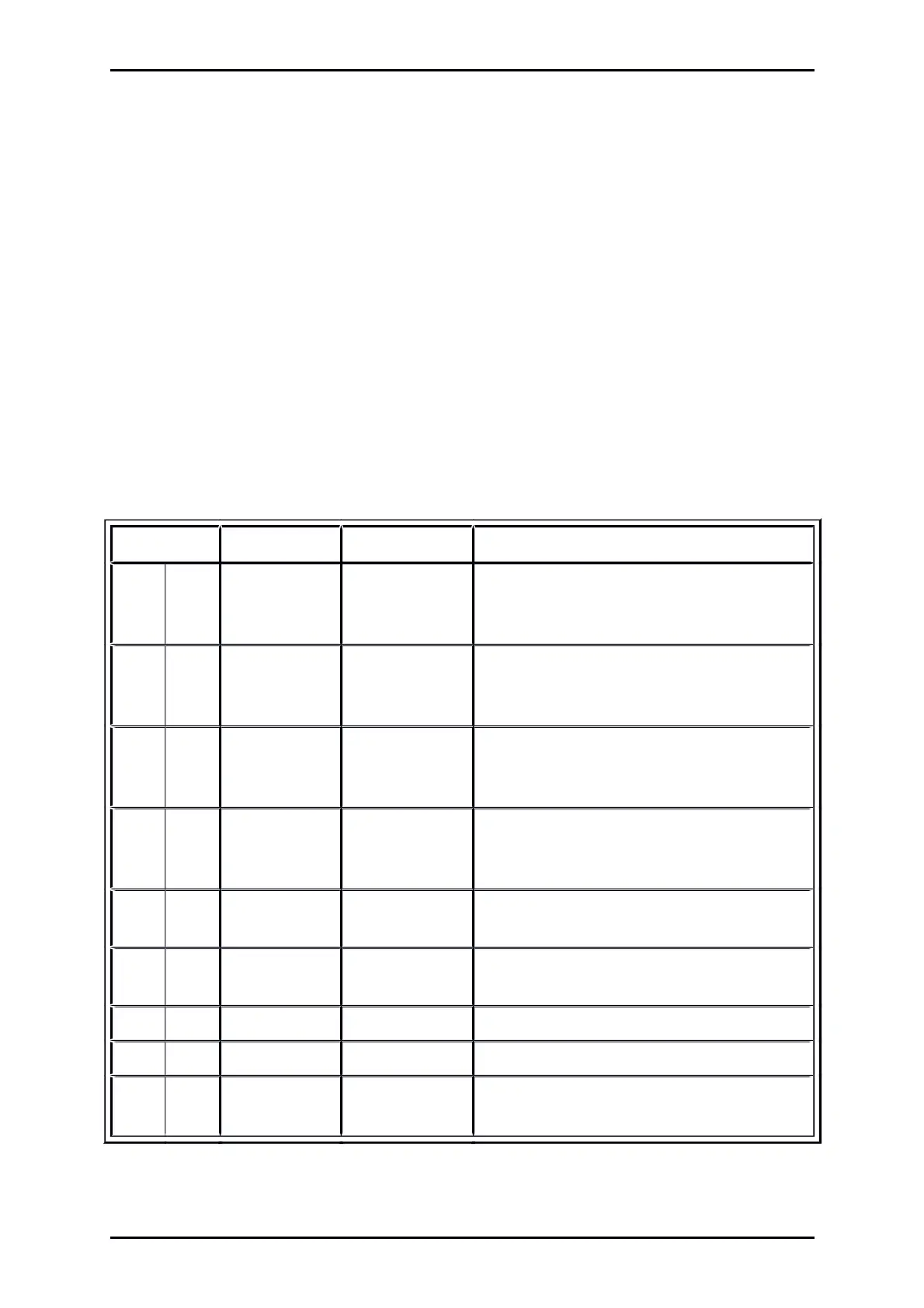
8.8.3 Pin assignment [X10]
Table 38: Pin assignment: Incremental encoder input [X10]
Pin No Denomination Values Specification
1 A / CLK
5 V / R
I
120
Incremental encoder signal A /
Stepper motor signal CLK
pos. polarity as per RS422
6 A# / CLK#
5 V / R
I
120
Incremental encoder signal A# /
Stepper motor signal CLK
neg. polarity as per RS422
2 B / DIR
5 V / R
I
120
Incremental encoder signal B /
Stepper motor signal DIR
pos. polarity as per RS422
7 B# / DIR#
5 V / R
I
120
Incremental encoder signal B# /
Stepper motor signal DIR
neg. polarity as per RS422
3 N
5 V / R
I
120
Incremental encoder index pulse N
pos. polarity as per RS422
8 N#
5 V / R
I
120
Incremental encoder index pulse N#
neg. polarity as per RS422
4 GND Reference GND for encoder
9 GND Shield for the connection cable
5 VCC + 5 V / 5 %
100 mA
Auxiliary supply (short circuit-proof), load with
100 mA maximum!
Product Manual „Servo drives ARS 2100 SE“ Version 5.0
 Loading...


