Electrical installation Page 57
Product Manual / Mounting Instructions „Servo drives ARS 2320 FS, ARS 2340 FS and ARS 2360W FS“ Version 1.0
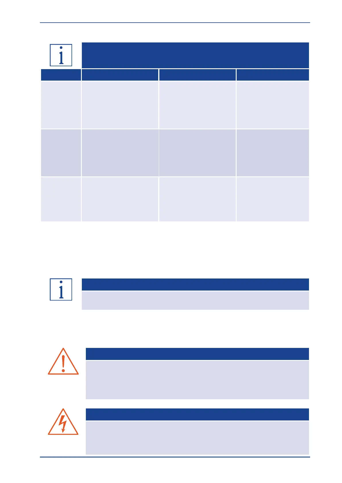
Phoenix Contact
SPC 5/ 4-STF-SH-7,62
(1704071) or
PC 5/ 4-STF-SH1-7,62
(1778191)
Phoenix Contact
SPC 16/5-ST-10,16
(1711297) or
PC 16/4-STF-SH-10,16
(1970359)
Phoenix Contact
PC 35 HC/ 4-STF-SH-
15,00 (1762848)
Phoenix Contact
FK-MCP 1,5/ 3-STF-3,81
(1851245) or
MC 1,5/ 3-STF-3,81
(1827716)
Phoenix Contact
FK-MCP 1,5/ 2-STF-3,81
(1851232) or
MC 1,5/ 2-STF-3,81
(1827703)
Connect the inner shields to X6A.PIN1; maximum length 100 mm.
Length of unshielded cores maximum 50 mm.
Connect total shield to X6 Shield terminal. Use cable strap to fix the shield on the connector.
Connect total shield on motor side flat to connector or motor housing; maximum length 40 mm.
The cable shield of the motor cable must also be connected to the controller
Shieldterminal on X6.
The Servo drive ARS 2300 FS must be connected to ground with its PE connection.
The ARS 2300 FS must be completely wired first. Only then the operating voltages for the DC bus and
the electronics supply may be switched on.
The servo drive will be damaged
• in the case of inversed wiring of the operating voltage connections,
• in the case of excessive operating voltage or
• in the case of confusing the connections for operating voltage and motor!
CAUTION! DANGEROUS VOLTAGE
The signals for the temperature sensor "MT+" (X6A.PIN2) and "MT-" (X6A.PIN3) on
the motor connector plug [X6] are not situated on safety extra-low voltage (PELV -
protective extra-low voltage). The connections are designed for non-PELV
temperature sensors. The isolation to PELV is part inside the ARS 2300 FS.
 Loading...

