264 Chapter 30: Input Channels
PRO1 Live Audio System
Operator Manual
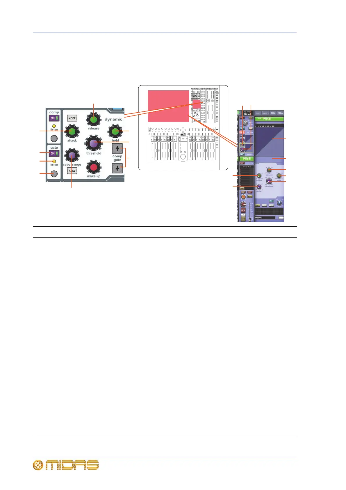
Gate
Unlike the compressor, gate mode has only one style. While the dynamic section is
addressing the gate, all of its controls are enabled except the make up control knob
and the MODE and KNEE buttons.
Item Description
1 Up/down select buttons, for swapping dynamic section control from compressor to
gate, and vice versa.
2 Gate range control knob, adjusts amount of gain reduction applied to the signal below
threshold. Controls the maximum gain reduction that is possible. Range is from minus
infinity (-∞) to zero.
3 Quick access button, which directly selects the compressor or gate processing areas on
the input channel strip.
4 To aid set up, the gate has a side chain listen that sends the side chain onto a solo bus.
This side chain listen LED indicator illuminates to warn you that soloed material is from
the side chain, and not the main channel. For information on the side chain, see “Side
chain” on page 265.
5 ON switch, enables gate in the signal path. When switched off, gate is bypassed. (Both
the comp and gate switches can be on at the same time.)
6 attack control knob, adjusts time taken for gate to open after an over-threshold signal.
Range is from 0.02ms to 20ms (milliseconds).
7 release control knob, adjusts time taken for gate to close after programme material
falls back below threshold. Range is from -0.005s to 2.000s (seconds).
8 threshold control knob, sets signal level at which gate opens. Range is from -50dB to
+25dB.
9 hold control knob, minimises chattering in conjunction with internal hysteresis. Once
the signal is detected as below threshold, this defines a waiting period before the gate
starts to close. Range is from -0.005s to 2.000s (seconds).
10 Gate meter.
11 Gate graph display. Similar to the compressor graph (see “About the compressor graph”
on page 262), this shows the effects of adjusting the gate control knobs.
D zone
1
6
2
5
4
3
7
9
8
11
1010
7
9
8
6
2
5 8