28 Chapter 4: Setting Up The System
PRO1 Live Audio System
Operator Manual
Connecting up
Connect your system according to your requirements. For examples of system
configuration, see “System configurations” on page 7.
To ensure the correct and reliable operation of your equipment, only high quality,
balanced, screened, twisted pair audio cable should be used.
XLR connector shells should be of metal construction so that they provide a screen
when connected to the console and, where appropriate, they should have Pin 1
connected to the cable screen.
All Jack connector shells should be connected to the cable screen.
Audio connections
This section gives details of the audio connections of the PRO1 Control Centre.
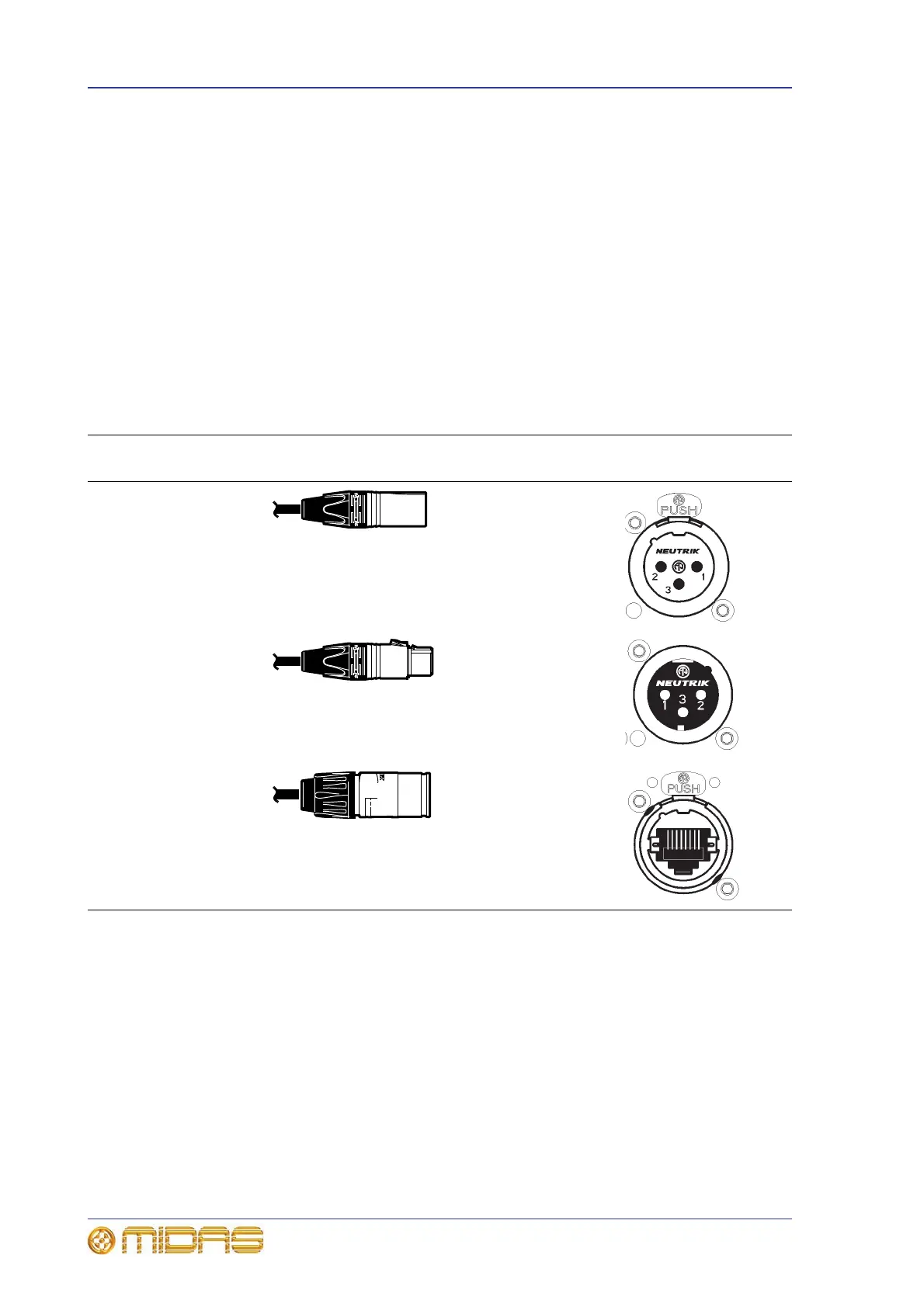
Table 1: Connector pinouts
Connector on rear
panel Example of plug Pinouts Example of socket
Male XLR chassis
connector (output)
1 = ground
2 = hot
3 = cold
Female XLR chassis
connector (mic input)
1 = ground
2 = hot
3 = cold
Ethernet EtherCon®
connector
N/A