OM-266409 Page 44
. Hardware is common and
not available unless listed.
1
7
2
3
5
9
6
271 902-B
4
10
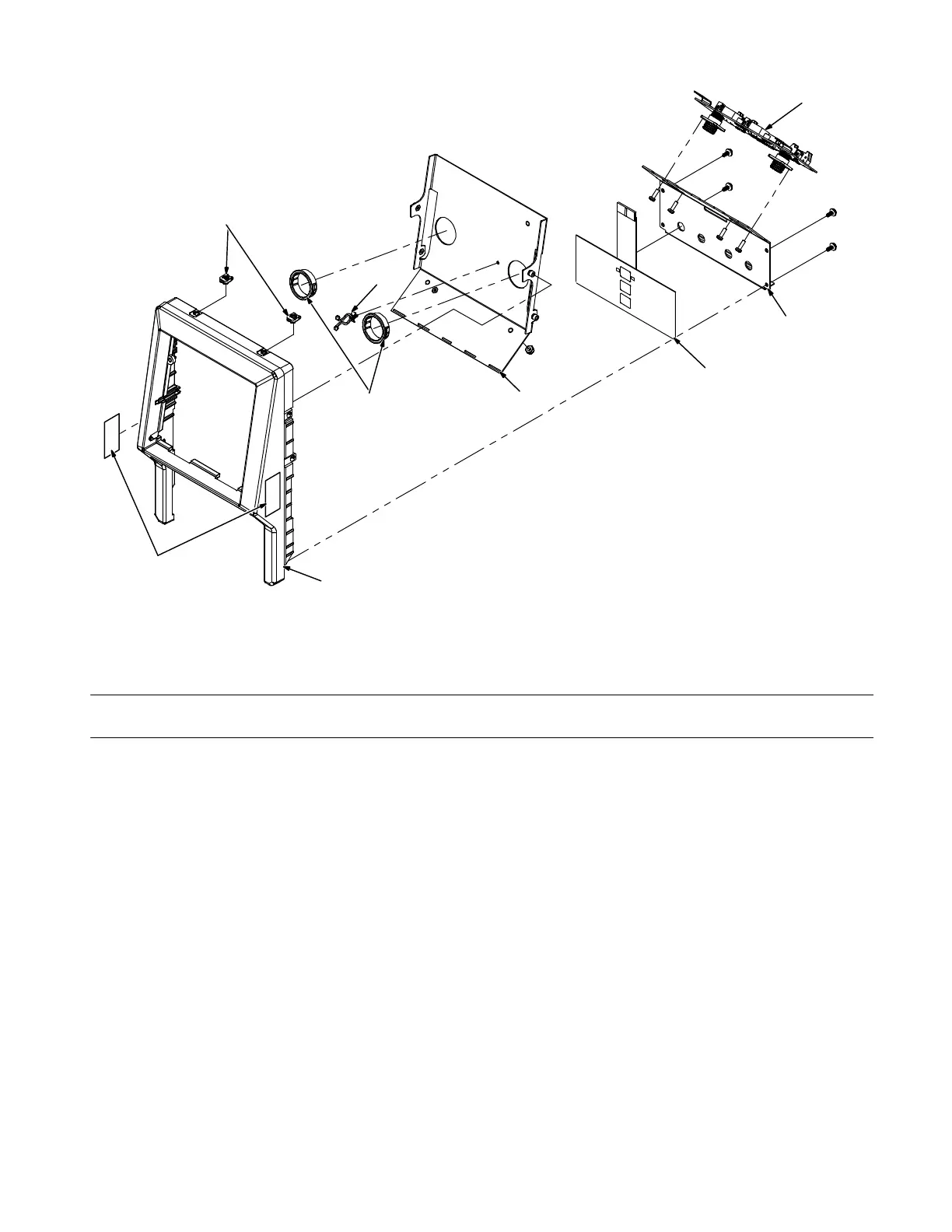
Figure 8-2. Front Panel Assembly
Description
No.
Mkgs.
No.
Figure 8-2. Front Panel Assembly (Figure 8-1, Item 10)
Quanti
1 266147 Plate, Trigger Dual 4pin 1... .......... .. ...........................................
2 276376 Membrane, Switch Control Continuum Feeder Single 1... .......... .. .................
3 +253528 Bezel, Feeder With Inserts 1... ......... .. ........................................
4 269731 Label, Warning Hot Surfaces And Moving Parts 2... .......... ... .....................
5 253628 Baffle, Front Panel 1... .......... .. ...............................................
6 170647 Bushing, Snap−In Nyl 1.062 Id X 1.500 Mtg Hole Cent 2... .......... .. ................
7 PC41 266157 Circuit Card Assy, Trigger Dual 4pin 1... .. . .. ................................
8 107983 Not Being Used... .......... ..
9 223343 Clip, Wire Stdf .40−.50 Bndl .156hole .031−.078thk 1... .......... .. ...................
10 207152 Nut, 010−32 U−Nut Multi−Thread 2... .......... .. ...................................
+ When ordering a component originally displaying a precautionary label, the label should also be ordered.
To maintain the factory original performance of your equipment, use only Manufacturer’s Suggested
Replacement Parts. Model and serial number required when ordering parts from your local distributor.