BeneVision N Series Patient Monitor Operator’s Manual 2 - 13
2.3.5.2 Example Module
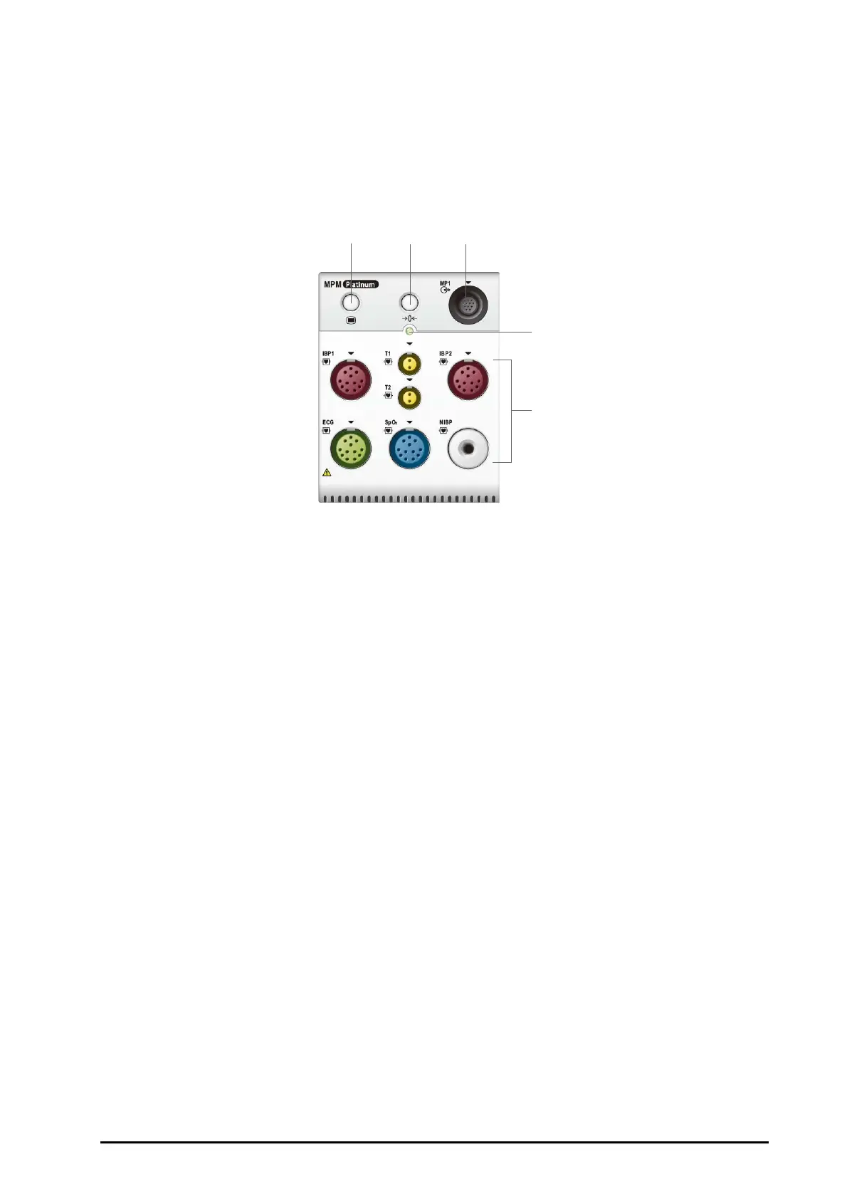
The parameter modules have similar structure:
■ The parameter label is marked at the upper left corner.
■ Hard keys are located on the upper part.
■ Patient cable connectors are located at the lower part.
We take the MPM module as an example.
(1) Setup hard key: enters or exits the MPM setup menu.
(2) Zero hard key: enters the Zero IBP menu.
(3) Analog out connector: outputs defibrillation synchronization pulse, ECG, and IBP analog
signal.
(4) Module status indicator
◆ On: the module works properly.
◆ Flashing: the module is initializing.
◆ Off: the module is not connected or the module fails.
(5) Patient cable connectors: the MPM module incorporates multiple measurement modules,
including ECG, Resp, SpO
2
, NIBP, Temp, and IBP.
 Loading...