Product Principle 4-1
4 Product Principle
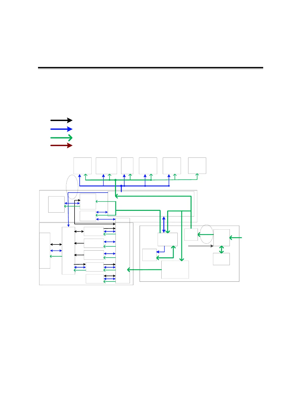
4.1 General Structure of Hardware System
Symbols illustration
Communication
&control
Power supply
Ultrasonic signal
Clock signal
Back -end mother board
ECG/PCG
board and
USB
extending
board
Control
panel
Display&
touch
screen
DVD-R/W
Back- end
power board
Battery
AC Input
Charge/
discharge
DC power
Signal port
Power supply unit
USB
Fan
Auxiliary output control
Isolation
transformer
Power
supply
connecting
board
AC-DC
power
board
Probe
board
Front-
end
analog
mother
board
CW board
Transmission
board A
Transmission
board B
Receiving
board
Signal
processing
board
Commu
nication
mother
board
Front- end power
board
(main/auxiliary)
Digital
board
4D or
4D&TEE
board
Front- end unit
Back-end unit
cable
conne
ction
Ultrasound
Gel Heater
IO BOX
board
Back-
end
board
Figure 4-1 Schematic Diagram of System Hardware
As described in the figure above, the hardware consists of the following units:
Front-end unit (probe board, CW board, transmission board A, transmission board B,
receiving board, Signal processing (DSP) board, front-end analog motherboard,
communication motherboard)
Back end unit (digital board, 4D or 4D&TEE board, IOBOX board, back end motherboard);
Control panel unit;
Main display unit;
Touch screen unit;
ECG/PCG board;