Product Principle 4-9
4.3 Ultrasound Back-end Unit
The back-end unit mainly consists of: digital board, back-end motherboard, IOBOX board, 4D, etc.
See the figure below:
Multi-
function
FPGA
Digital board
COM-E
CPU module
PCIE
To signal
processing board
Back-end
motherboard
IO BOX board
HDMI
DVI ……..
Video-out Video-in SVideo-in
SVideo-outUSBUSB
Communication
motherboard
4D or 4D&TEE
board
Fig 4-11 Schematic Diagram of Back-end Unit
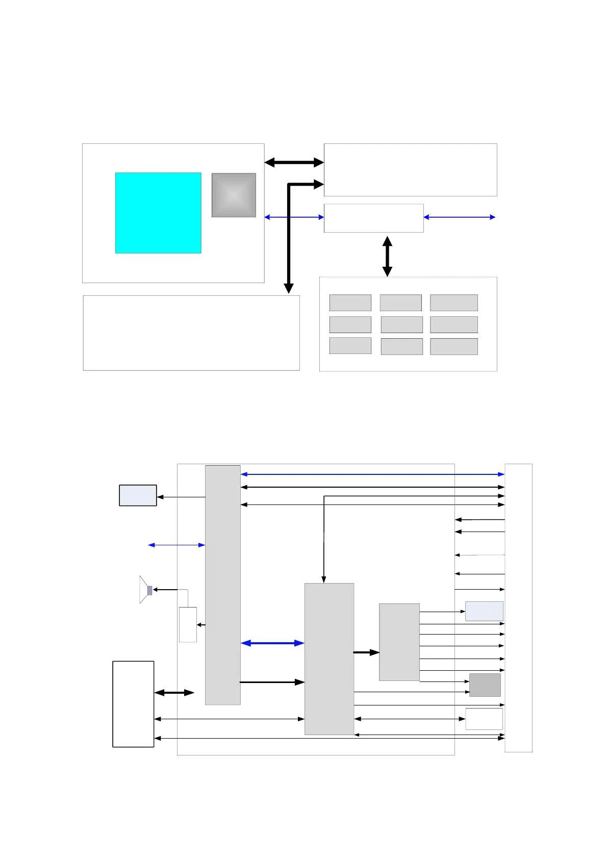
4.3.1 Digital Board
The block diagram of the digital board is shown as below:
Video
transfer
Multifunction
FPGA
COM-E
CPU
module
DVI
VGA
HDMI
S-Video
CVBS
Serial port
remote_Print_C
VGA
1Gbit Ethernet
USB port
Audio out
Audio
output
Dual speaker
PCIE
Control bus LPC
CVBS Video in
S-Video in
Audio in
MIC in
DVI
IO
BOX
CVBS
Main
display
LCD
PCIE X1 for WLAN
B/W
video
print
Touch
screen
USB
UART X2
Back-end
power
board
SMBUS for WLAN
To
Front-end
unit
boards
Data bus LVDS
Digital board
remote_Print
Temperature monitor and
clock enable signal
ECG control signal etc.
Sound
card
Fig 4-12 Schematic diagram of the digital board