4-14 Product Principle
Fig 4-16 Back-end Motherboard Connection
The figure above shows the cable and socket connection on the back-end motherboard, and the
connection with the other boards and modules.
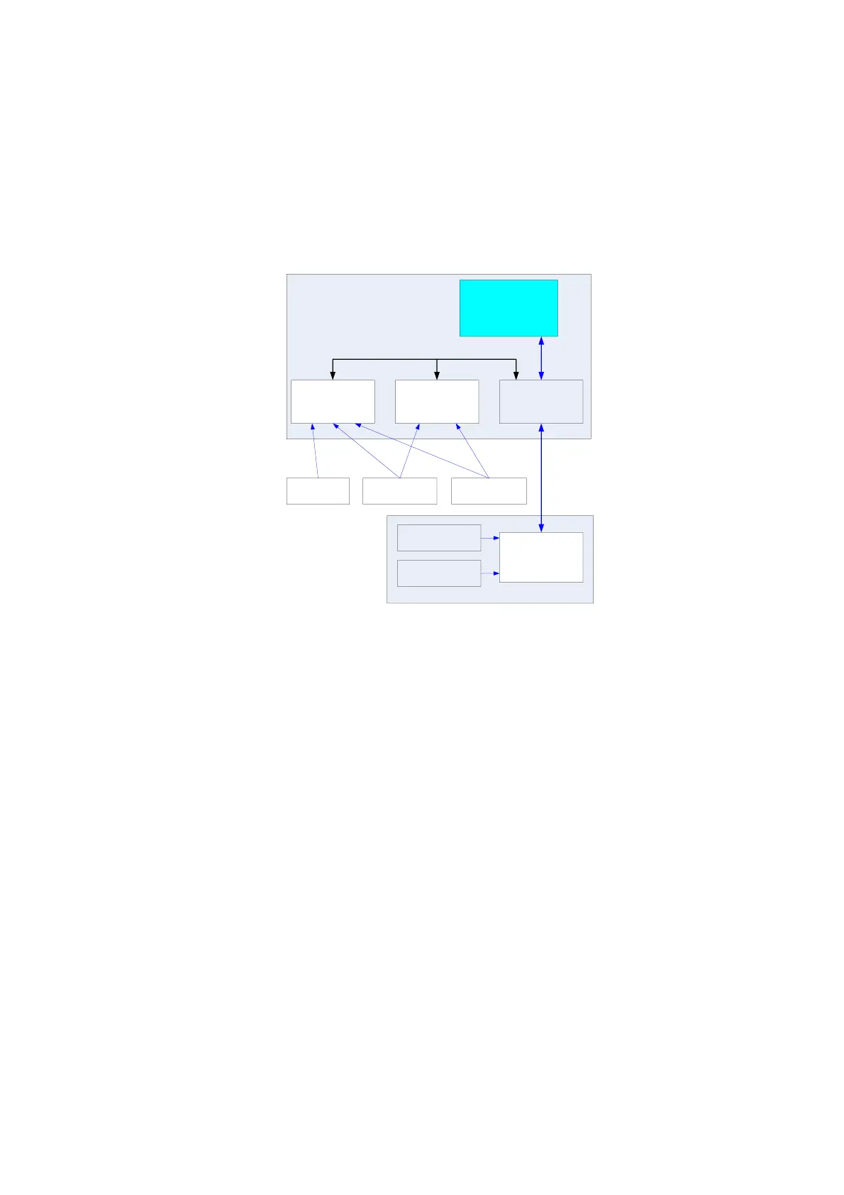
4.3.6 Ultrasound System Monitoring
CPU module
ADT7462(A)
SMBUS1
ADT7462(B)
Multifunction FPGA
LPC
ADT7462(C)
SMBUS2
Temperatures in
the front end power
Voltages in the
front end power
Back end
power
Temperatures in
the main unit box
Fans in the main
unit box
Digital board
Front end power board
Fig 4-17 Block Diagram of Ultrasound system monitoring
Function description:
Use ADT7462 chip to monitor system voltage, temperature and fans, Circuit structure is
shown in the figure above.
The communication between CPU and ADT7462 is realized by the SMBUS supported by
FPGA.
Two pieces of ADT7462 on the digital board are used for main unit box fan, back-end
power monitor and main unit box temperature monitoring.
1 piece of ADT7462 on the front-end power board is used for front-end power monitor and
temperature monitoring.