2 System Overview
Operator’s Manual 2 - 31
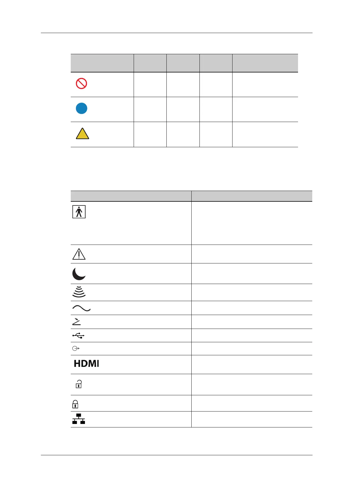
2.16 Symbols
This system uses the symbols listed in the following table. Their meanings are explained as follows:
Geometric shape Meaning Safety
color
Contrast
color
Graphical symbol
color
Prohibition Red White Black
Mandatory
action
Blue White White
Warning Yellow Black Black
Symbol Description
Type-BF applied part
The ultrasound probes connected to this system
are type-BF applied parts.
The ECG leads within this system is type-BF
applied part.
Caution!
Standby
Transducer sockets
AC (Alternating current)
Foot switch
USB port
Extending port
Hi
gh definition multimedia interface
Unlock position
Lock position
Network port