EasyManuals Logo

Mindray M9 User Manual

Mindray M9
267 pages
To Next Page IconTo Next Page
To Previous Page IconTo Previous Page
Page #167 background imageLoading...
Page #167 background image
Structure and Assembly/Disassembly 8-37
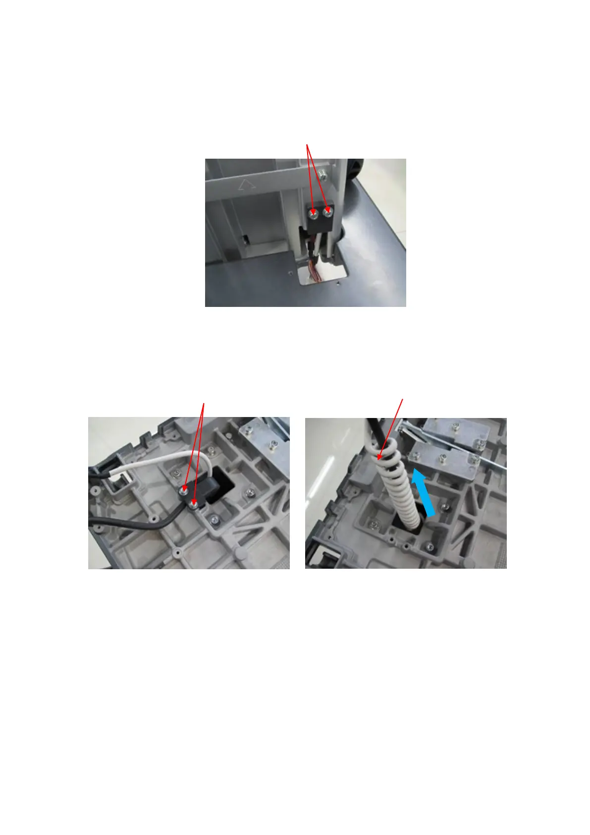
Unscrew 2 screws (M4 X 12 cross panhead screw) on the injection-molding clasp of spring
cable on the base.
Unscrew 2 screws (M4 X 12 cross panhead screw) on the base of control panel, and take
out the panel cover.
5. Remove the connecting rod of gas spring.
Press gas spring button (the sixth step), remove the handle upwards. Release the spring to the
maximum length (operable to remove gas spring assembly). Put the auxiliary tool (M5 screw or
screw driver) into the spacing hole on the back of the device (operable to remove trolley panel
board).
M4X12 cross panhead
screw (2 screws)
Take out the spring cable
upwards
M4X12 cross panhead screw
(2 screws)

Table of Contents

Questions and Answers:

Question and Answer IconNeed help?

Do you have a question about the Mindray M9 and is the answer not in the manual?

Mindray M9 Specifications

General IconGeneral
TypePortable Ultrasound System
BatteryRechargeable lithium-ion battery
Battery LifeUp to 90 minutes
Display15.6 inch high resolution LED monitor
Imaging ModesB, M, Color, Power, PW, CW
TransducersLinear, Convex, Phased Array
Transducer Ports3
Probe Connectors3
ConnectivityDICOM, USB, HDMI
Operating SystemWindows-based

Related product manuals