3.2 NMI Interrupts
MIPS® Malta™ User’s Manual, Revision 01.07 15
Copyright © 2000-2007 MIPS Technologies Inc. All rights reserved.
3.2 NMI Interrupts
There are two sources of NMI:
• ON/NMI push button
• South Bridge due to assertion of PCI SERR (from PCI slot or Core card) or assertion of ISA IOCHK.
When the ON/NMI push button is activated, the signal is debounced and latched in the NMI interrupt controller. The
South Bridge NMI is routed through the NMI controller as it is. These signals then generate an active state on the
NMIN pin of the MIPS Core Board. The NMISTATUS register can be read to determine the cause of the NMI.
3.3 NMI Acknowledge
The ON/NMI interrupt is by nature transient. Therefore it is debounced and latched and thereafter treated as an ordi-
nary level-based interrupt in the NMI interrupt controller. The NMI interrupt can be cleared by writing a “1” to the
NMIACK register. Note that South Bridge NMI is acknowledged in the South Bridge.
7:4 PROID 4-bit binary number gives product ID 0x2
3:0 PRORV 4-bit binary number gives product revision. n/a
Name: NMISTATUS
Address: 0x1F00.0024
Access: RO
Reset Value: n/a
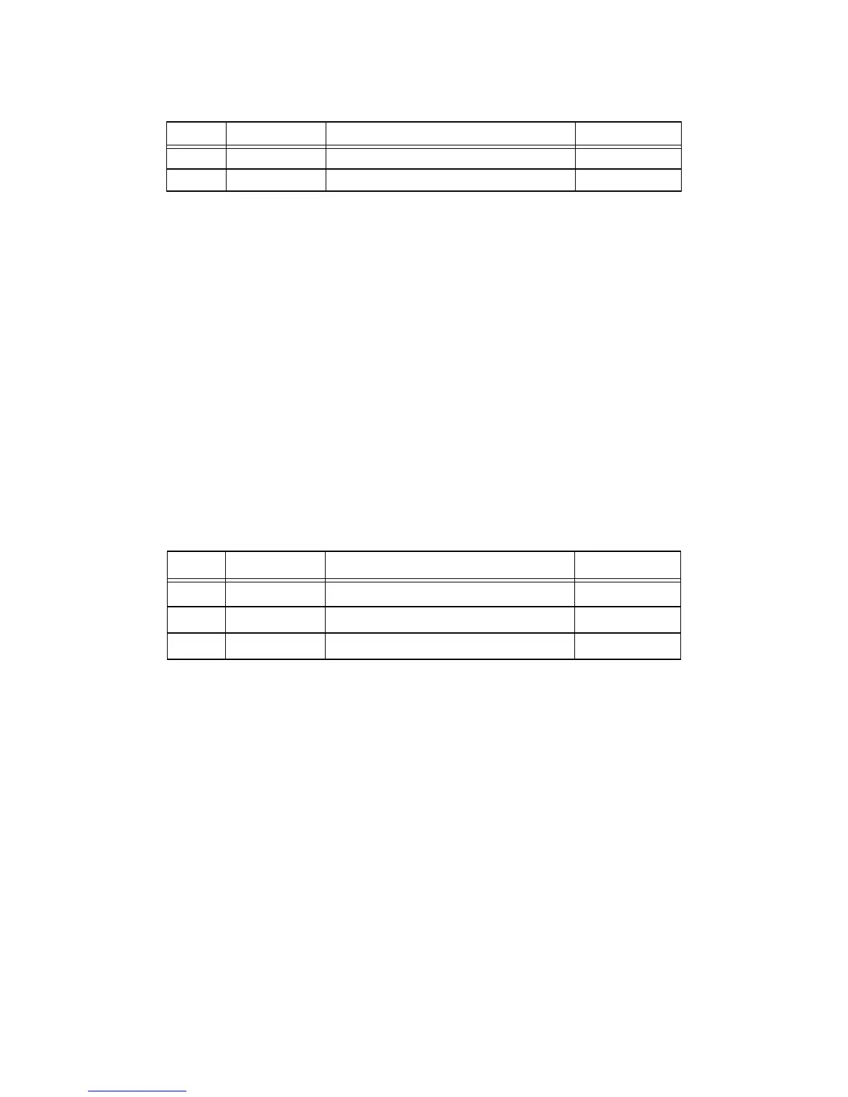
Table 3.4 NMISTATUS Register
Bits Field Name Function Initial Value
31:1 Reserved Reserved n/a
1 SB Pending NMI from the South Bridge n/a
0 ONNMI Pending NMI from the ON/NMI push button n/a
Name: NMIACK
Address: 0x1F00.0104
Access: WO
Reset Value: n/a
Table 3.3 REVISION Register (Continued)
Bits Field Name Function Initial Value