7.3 Physical Design
MIPS® Malta™ User’s Manual, Revision 01.07 57
Copyright © 2000-2007 MIPS Technologies Inc. All rights reserved.
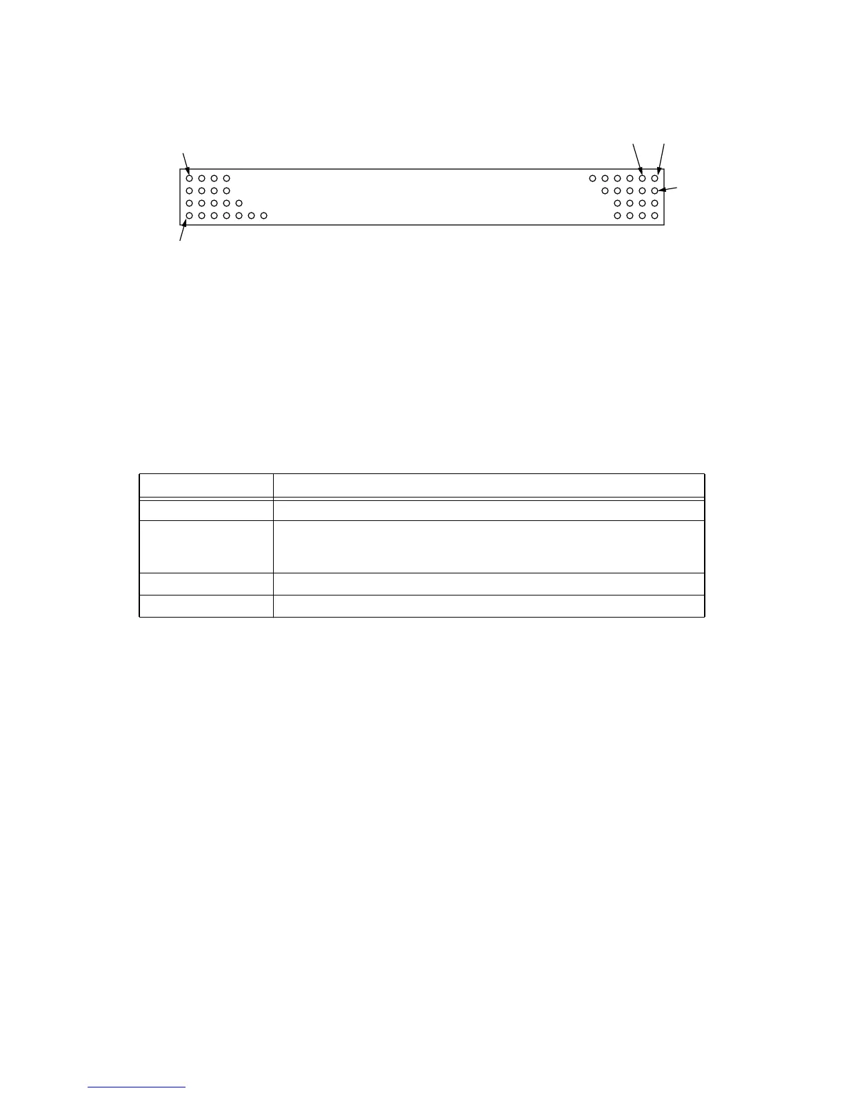
Figure 7.3 J3 and J4 Alignment
Note that one corner pillar (top left in figure) is placed offset from a symmetrical position, which is to guarantee the
board cannot be inserted the wrong way around.
The connectors chosen are low-insertion force. You should be able to “lever” the card up by placing a screwdriver
between the mounting pillars and the card.
The Core card is mounted at a height of 11mm over the motherboard when using the connectors given above. How-
ever, the existing placement of high components on the Atlas and Malta motherboards results in the height restric-
tions when placing components on the Core board, as shown in Table 7.5.
Table 7.5 Core Card Component Height Restrictions
Location Height Restrictions on Underside
Whole card (default) No underside SMDs thicker than 6.5mm
Zone 1 No leaded components at all. No underside SMDs thicker than 1.2mm. (Note: this
requirement applies only to Core cards that must be compatible with Atlas. Malta
does not have this restriction.)
Zone 2 No underside SMDs thicker than 4.4mm
Zone 3 No underside SMDs thicker than 4.4mm
21
50
51
200