Hardware Description
36 MIPS® Malta™ User’s Manual, Revision 01.07
Copyright © 2000-2007 MIPS Technologies Inc. All rights reserved.
IRQ 0..15 are prioritized in the sequence : 0, 1, 8..15, 3..7. IRQ 2 is reserved for cascading the two 82C59 devices that
together constitute the South Bridge Interrupt Controller.
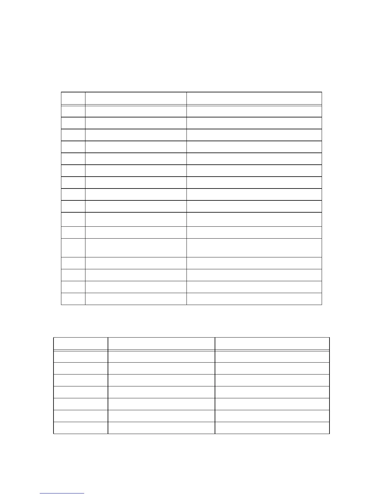
The mapping of IRQ 0..15, as used by YAMON, is shown in Table 5.2.
The mapping of CPU INT0..5 and CPU NMI is shown in Table 5.3.
Table 5.2 IRQ 0..15 Mapping
IRQ # Source(s) Device(s)
0 Timer South Bridge
1 Keyboard SuperI/O
2 Reserved by South Bridge (for cascading)
3 UART (tty1) SuperI/O
4 UART (tty0) SuperI/O
5 Not used
6 Floppy Disk SuperI/O
7 Parallel port (1284) SuperI/O
8 Real Time Clock South Bridge
9
I
2
C bus
South Bridge
10 PCI A, PCI B (including Ethernet) PCI slot 1..4, Ethernet
11 PCI C (including audio),
PCI D (including USB)
PCI slot 1..4, Audio, USB (South Bridge)
12 Mouse SuperI/O
13 Reserved by South Bridge
14 Primary IDE Primary IDE slot
15 Secondary IDE Secondary IDE slot/Compact flash connector
Table 5.3 CPU INT0..5 and CPU NMI Mapping
CPU INT/NMI Source(s) Device(s)
NMI South Bridge NMI or NMI button South Bridge or On/NMI Buttom
0 South Bridge INTR South Bridge
1 South Bridge SMI South Bridge
2 CBUS UART (tty2) Discrete 16550
3 COREHI Core Card
4 CORELO Core Card
5 Not used, driven inactive Typically used for CPU internal timer interrupt