4.3 Displays / LEDs
MIPS® Malta™ User’s Manual, Revision 01.07 29
Copyright © 2000-2007 MIPS Technologies Inc. All rights reserved.
DIP switches S2, S5-2, S5-3, and S5-4 are readable by software.
For the DIP switches S2 & S5, a switch referred to as “1” is marked by a dot or by a “0” in the silkscreen, or the
switch is marked by a “1”.
4.3 Displays / LEDs
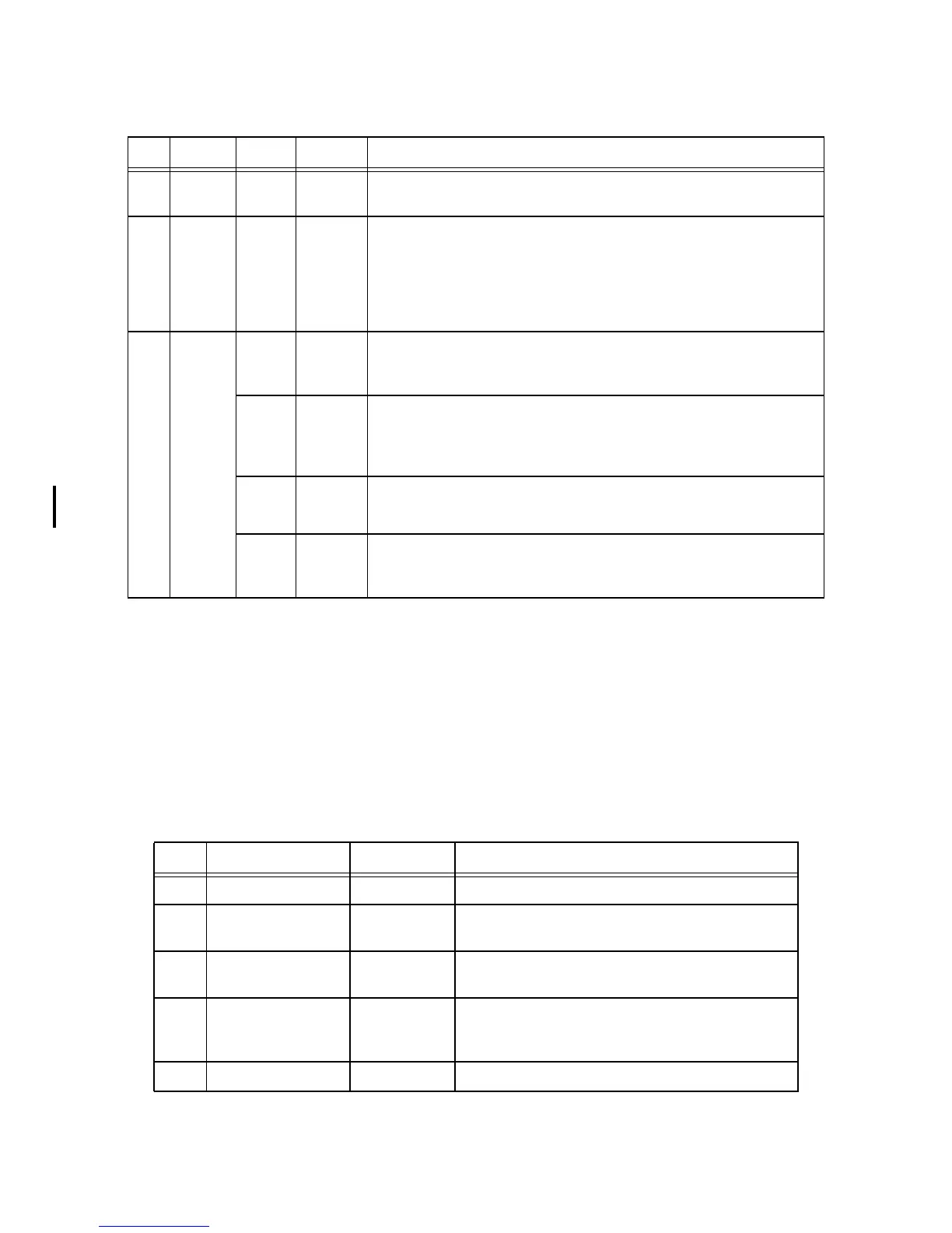
The Malta Board has two displays and various individual status LEDs., described in Table 4.4. See also Section 3.5,
"Displays".
S3 Push-
button
n/a Reset button.
S4 Push-
button
n/a NMI/Power ON button. This button will bring the ATX power supply out of
stand-by. It also generates an NMI to the CPU, for example, to shut down the
PSU again.
This button causes a hardware shutdown if pressed for more than four seconds
at a PCI clock at 33MHz. For PCI clocks below 33.33 MHz, the button has to
be pressed for a longer period of time (up to 12 seconds).
S5 4-way
DIP
S5-1 OFF When ON, enables Flash programming via 1284 parallel port.
This swithch enables writing to the Monitor Flash lock bits. It overrides
Jumper JP1.
S5-2 OFF When ON, set operation mode to big endian.
If the endianess is changed, Malta must be reset again in order for the new
endian mode to take effect.
If the board is not reset unpredictable operation can occur.
S5-3 OFF If S5-3 is enabled and an SMP/CMP processor is detected (34K/1004K),
YAMON will initialise all CPUs and place them in an idle loop early on in the
initialisation.
S5-4 OFF When ON at power-on or at reset, sets YAMON in factory default mode e.g.,
communication on tty0 port is forced to 38.4 kbaud, 8 bits/char, RTS/CTS
hardware handshaking and no parity.
Table 4.4 LEDs
Ref Silkscreen Type Description
D28 n/a 8-way bar Controlled by software.
U42 n/a 8 char ASCII
display
Used by YAMON to display status.
Can be used for any user purpose.
D7 ATX ON Green SMD Indicates that power is applied to the ATX power-supply.
Also lit when board is in stand-by mode.
D2 STBY Green SMD Indicates that power is applied to 3V3STBY (+/-5%) and
5VSTBY (+/-5%). Not led when board is in stand-by
mode.
D6 5V Green SMD Indicates that power is applied to 5V (+/-5%).
Table 4.3 Switches (Continued)
Ref Type Default Description