Hardware Description
40 MIPS® Malta™ User’s Manual, Revision 01.07
Copyright © 2000-2007 MIPS Technologies Inc. All rights reserved.
5.15 AMR (Audio Modem Riser)
Connector J16 is an AMR connector [14] that allows an audio/modem interface card to be plugged into the mother-
board. This is controlled via U23, a PCI Audio controller [7]. The AMR connector is a dual AC’97 audio codec inter-
face.
5.16 Front Panel Connector
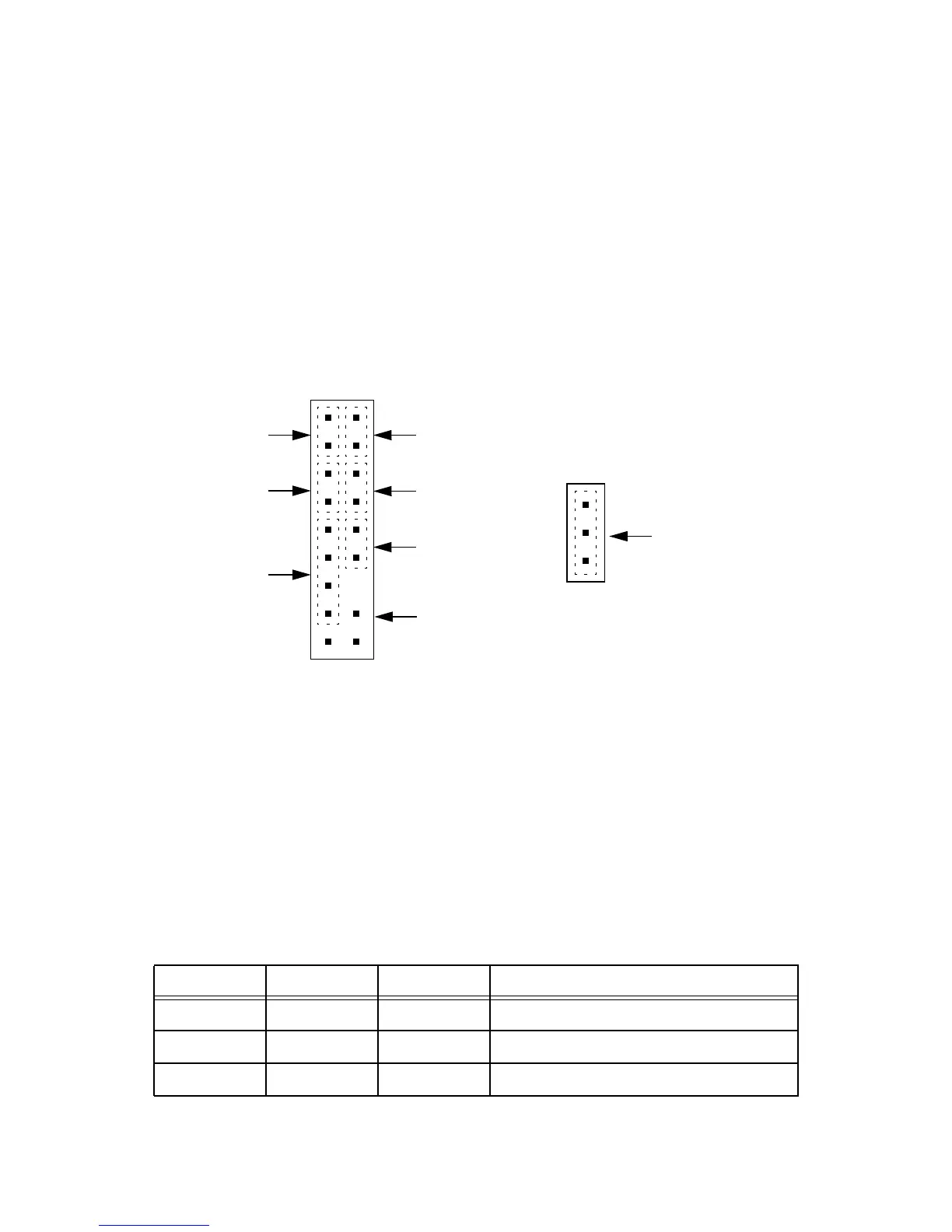
The Front Panel connector (J9), shown in Figure 5.3, contains all signals to/from the front panel of a normal PC-chas-
sis. An additional connector (J30) is available for a three-pin Power LED connector.
Figure 5.3 Front Panel Connector
5.17 Debug Access
5.17.1 Software Debug
The EJTAG connector (J17) allows connection of a suitable EJTAG debugger probe directly to the CPU. This allows
access to the internal hardware debug functionality of the CPU core. See [4] for details.
5.17.2 Hardware Debug
You have access to most, if not all, interesting signals on the Malta Board via testpoints (Table 5.5) and HP Logic
Analyser high-density connectors (Table 5.6). Refer to the tables below and the schematics for details of these.
Table 5.5 Testpoints
Ref Silkscreen Color Function
TP1 D3V3SB Red Digital 3.3V Stand-by
TP2 D5VSB Red Digital 5V Stand-by rail
TP3 D3V3 Red Digital 3.3V rail
12
++
Power LED
On/NMI Button
Reserved
HD LED
Reset Button
Reserved
+5V
+
Power LED
-
1
J30
J9