Chapter 5
MIPS® Malta™ User’s Manual, Revision 01.07 31
Copyright © 2000-2007 MIPS Technologies Inc. All rights reserved.
Hardware Description
This chapter describes the Malta Board’s hardware components. For more detailed information on these components,
refer to the Malta Schematics [16].
5.1 PCI Bus
The PCI bus is implemented as a 5V, 32-bit and 33 MHz PCI standard version 2.2 compliant bus [1] that connects the
main components on the Malta Board.
The devices on the PCI bus are:
• Core Board connector for connection to the system controller on the Core Board
• Intel PIIX4E South Bridge, 82371E (U9)
• AMD Ethernet controller, Am79C973 (U41)
• Crystal Audio controller, CS4281 (U23)
• Four 5V, 32-bit PCI connectors (J12-J15) that can be used for debug and trace and/or for installation of PCI
boards
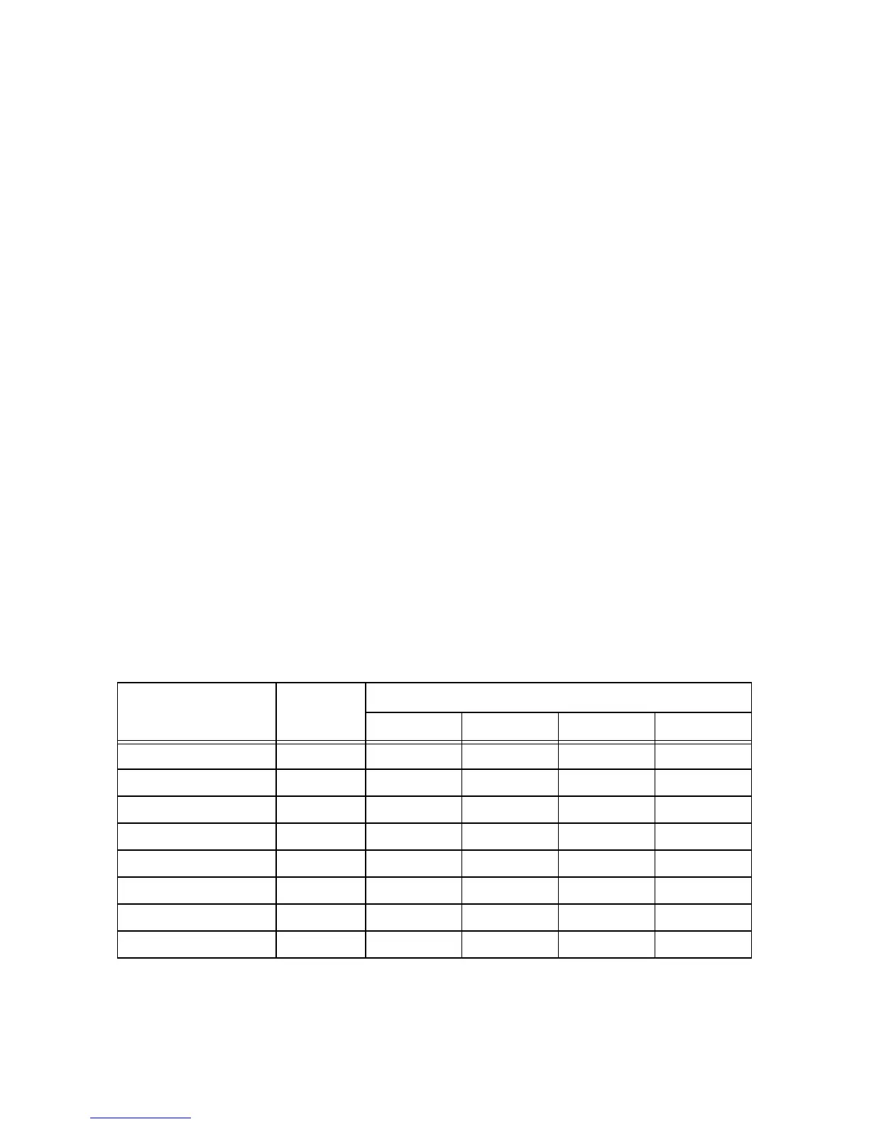
For configuration purposes, the IDSEL and INT# signals to the PCI devices are connected as shown in Table 5.1.
Table 5.1 IDSEL and INT# for PCI Devices
Device
IDSEL PCI
Address
PCI Interrupts Mapping
PCI_INTAN PCI_INTBN PCI_INTCN PCI_INTDN
South Bridge PCI_ADP20 USB_IRQ#
Ethernet controller PCI_ADP21 ETHER_IRQ#
Audio controller PCI_ADP22 AUDIO_IRQ#
Core Card PCI_ADP27
PCI Connector 1 PCI_ADP28 INTA# INTB# INTC# INTD#
PCI Connector 2 PCI_ADP29 INTD# INTA# INTB# INTC#
PCI Connector 3 PCI_ADP30 INTC# INTD# INTA# INTB#
PCI Connector 4 PCI_ADP31 INTB# INTC# INTD# INTA#