Board Layout
28 MIPS® Malta™ User’s Manual, Revision 01.07
Copyright © 2000-2007 MIPS Technologies Inc. All rights reserved.
Note 1: Only 10BASE-T is supported (100BASE-TX is not supported).
Note 2: Some Core Boards cannot run with a PCI clock frequency of 33.33 MHz. See the respective Core Board
User’s Manuals for maximum clock frequency.
4.2 Switches
Malta’s switches are described in Table 4.3. For those switches that are software-readable, a switch in position “ON”
or “CLOSED” (not in the “OPEN” position) will give a “1” in the appropriate register.
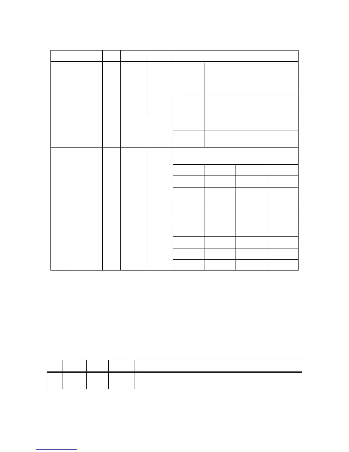
JP2 EEWR 2 fit - notfit notfit When fitted
Enables writing to the I
2
C EEPROM
(U14).
Do NOT fit this - it is reserved for produc-
tion use.
When not
fitted
Disables writing to the
I
2
C EEPROM
(U14).
JP3 CF MASTER 2 fit - notfit notfit When fitted Sets Compact Flash module as Master
IDE drive on the secondary IDE bus.
When not
fitted
Sets Compact Flash module as Slave IDE
drive on the secondary IDE bus.
JP4 PCI CLK 6 10 - 37.5
33.33
(2)
Sets PCI clock- frequency between 10MHz - 37.5MHz.
“X” = fitted.
MHz/Pins 1-2 3-4 5-6
10
(1)
XXX
12.5
(1)
X
16.67
(1)
XX
20
(1)
X
25
(1)
X
30
(1)
XX
33.33
37.5 X X
Table 4.3 Switches
Ref Type Default Description
S2 8-way
DIP
All OFF This switch provides a value which can be read from the SWITCH register.
Table 4.2 Jumpers (Continued)
Ref Silkscreen Pins Options Default Description