3.9 I2C
MIPS® Malta™ User’s Manual, Revision 01.07 21
Copyright © 2000-2007 MIPS Technologies Inc. All rights reserved.
3.9 I
2
C
I
2
C bus access registers. As both lines have an open-drain output, no conflicts can occur during direction shift on the
bi-directional lines.
There are three registers for I
2
C control:
• I2CINP: Reads input values.
• I2COE: Controls output enables
• I2COUT: Controls output values.
and one register for selecting the I
2
C controller:
• I2CSEL: Selects between the FPGA I
2
C controller and the South Bridge I
2
C controller (the two I
2
C controllers
cannot co-exist).
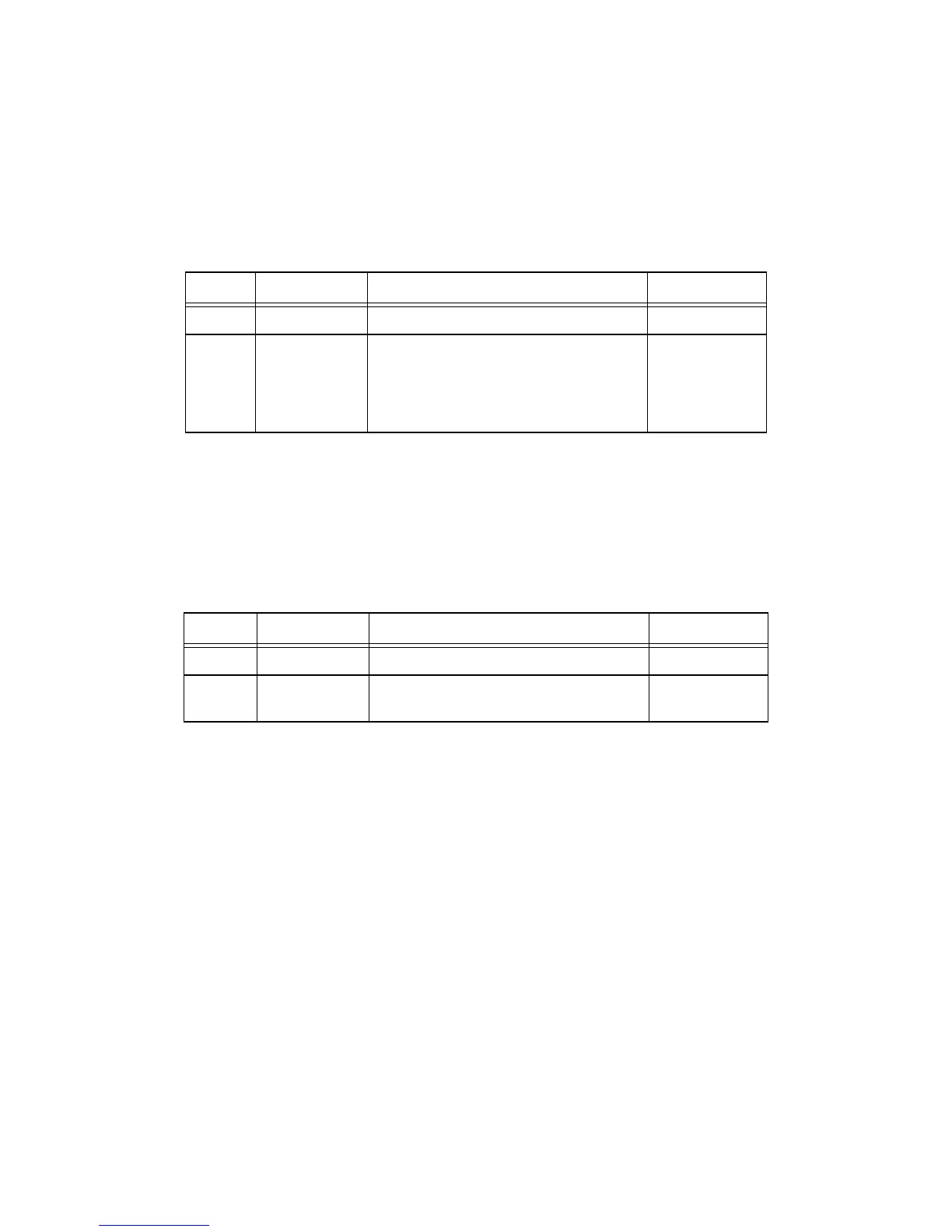
Name: GPOUT
Address: 0x1F00.0A00
Access: R/W
Reset Value: n/a
Table 3.16 GPOUT Register
Bits Field Name Function Initial Value
31:8 Reserved Reserved n/a
7:0 OUTVAL Writing to this address sets the 8 GP output
pins.
Reading gives the actual setting of the GP out-
put pins.
Functionality is Core Board dependent.
0
Name: GPINP
Address: 0x1F00.0A08
Access: RO
Reset Value: n/a
Table 3.17 GPINP Register
Bits Field Name Function Initial Value
31:8 Reserved Reserved 0
7:0 INPVAL Reading gives the actual state of the GP input
pins. Functionality is Core Board dependent.
n/a