Board Layout
30 MIPS® Malta™ User’s Manual, Revision 01.07
Copyright © 2000-2007 MIPS Technologies Inc. All rights reserved.
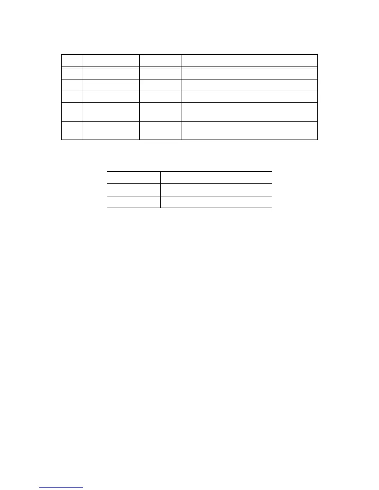
The two LEDs, described in Table 4.5, are built-in to the RJ45 connector J5 and display status.
All four ethernet LEDs are programmed/controlled by the ethernet controller. LED0-LED3 are linked to the four
LEDs.
D4 3.3V Green SMD Indicates that power is applied to 3.3V (+/-5%).
D5 FPGA Green SMD Indicates that CBUS FPGA programming completed OK.
D9 RST Red SMD Indicates that RSTN is active.
D1 TX Yellow SMD Ethernet LED3: Blinks on TX Ethernet packets (Program-
mable).
D3 SPD100 Green SMD Ethernet LED2: ndicates that 100 Mbit speed is selected
(Programmable).
Table 4.5 Ethernet Connector LED Functionality
LED Function
Green Ethernet LED0: Link up (Programmable)
Yellow Ethernet LED1: Activity (Programmable)
Table 4.4 LEDs (Continued)
Ref Silkscreen Type Description