Chapter 4 Mx-Series Unit Description 4-
23
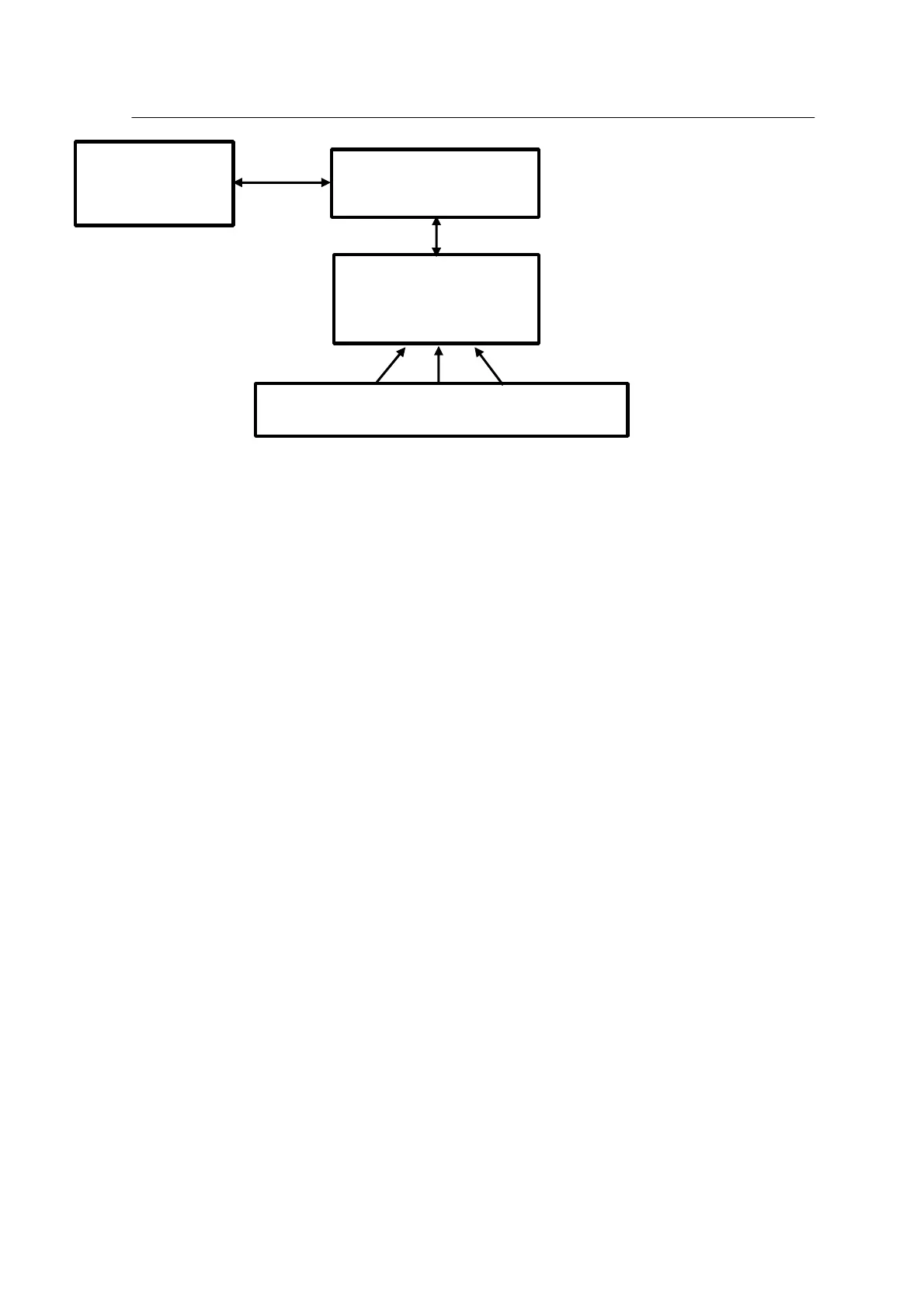
<Figure 4-12 Mx-Series vision system block diagram >
• Functions
− Component Recognition Camera
The upward looking cameras are used to check the component and recognize damage and
direction of the component. This information is transmitted to the host (VME) to carry out
component pick and place exactly.
The upward camera is a 3-Module CCD type composed of three CCD units.
− Teaching and Mark Inspection Camera
The vision system employs a Downward Looking Camera integrated with a head to
recognize the PWB fiducial mark or mark offset, to carry out compensation by automatic
PWB board width adjustment and to recognize the component pick-up position. This camera
is also used for position teaching.
• Positioning operation of vision system
The following gives a more detailed description of the process from component picking up to
placing or discarding described in the operation flow section of this chapter.
1. The head moves to the component pick-up position at the feeding part.
2. The head nozzle picks up the component.
3. After picking up the component, the head moves to the upward camera position.
4. The upward camera vision system determines the center of the component and offset
from the center of nozzle. The values determined include X-axis, Y-axis and R-axis (rotation)
values of the component. The vision system also inspects defects of the component.
5. The head moves to the placement position above the PWB.